Qwiic Human Presence Sensor (AK9753) Hookup Guide
 Englandsaurus
Hardware Overview
Listed below are some of the characteristics and operating ranges of the AK9753 Human Presence Sensor.
| Characteristic | Range |
|---|---|
| Operating Voltage | 3.3V |
| Operating Temperature | -30°C to 85°C |
| Current Consumption | 10 μA (typ.), 100 μA (max) (5V) |
| Spectral Sensitivity | 5-7 μm (5V) |
| Detection Range | 3 m (5V) |
| Temperature Sensor Range | -10° to 60°C |
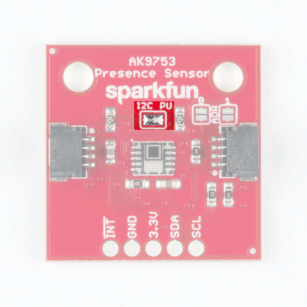
Pins
| Pin | Description | Direction |
|---|---|---|
| GND | Ground | In |
| 3.3V | Power | In |
| SDA | Data | In |
| SCL | Clock | In |
| INT | Interrupt, goes high when data is ready. After data is read, the pin pulls low | Out |
Optional Features
There are several jumpers on board that can be changed to facilitate several different functions. The first of which is the I2C pull-up jumper, highlighted below. If multiple sensors are connected to the I2C bus with the pull-up resistors enabled, the parallel equivalent resistance will create too strong of a pull-up for the bus to operate correctly. As a general rule of thumb, disable all but one pair of pull-up resistors if multiple devices are connected to the bus. If you need to disconnect the pull up resistors they can be removed by removing the solder from this jumper.
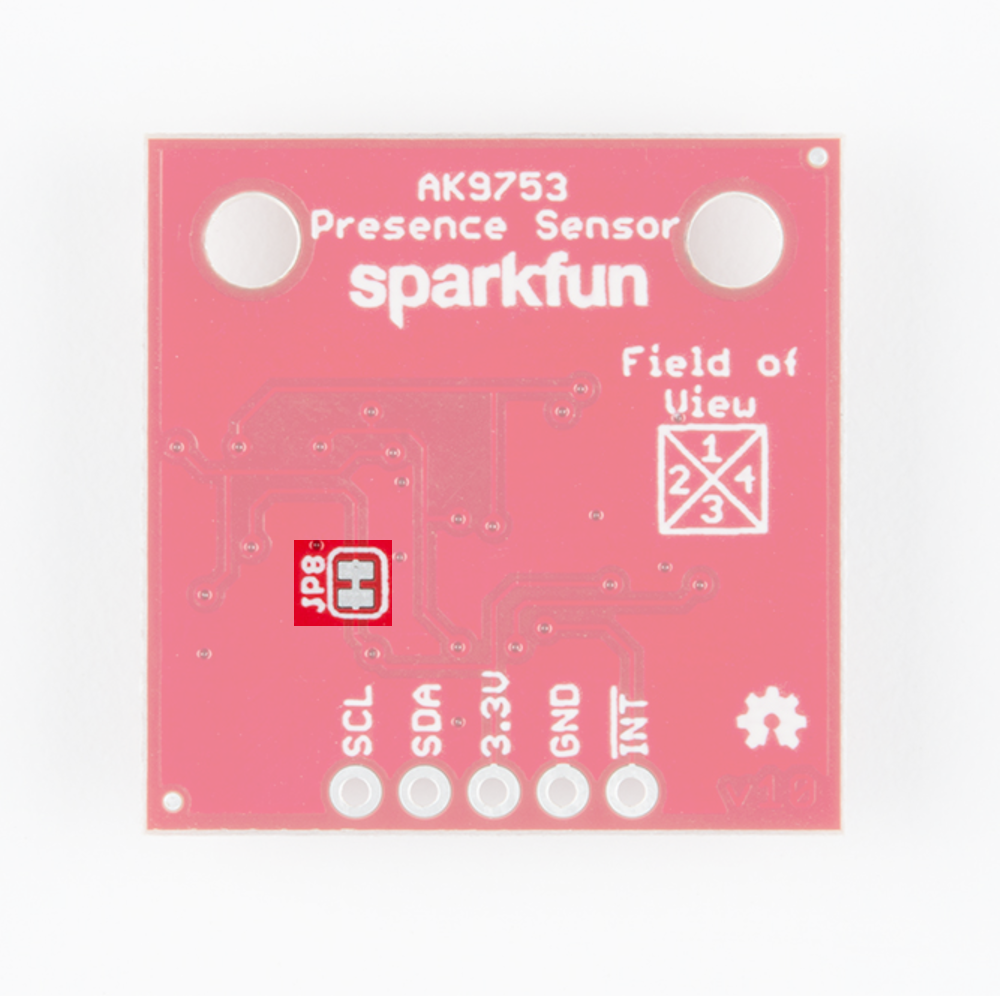
The JP8 jumper on the back of the board (highlighted below) can be sliced with a hobby knife to disable the interrupt capability. The "Field of View" text and box shows the field of view of each of the 4 sensors. From the sensor's point of view, channel 1 is on top, 2 is on left, 3 is on bottom, and 4 is on the right.
Addresses 0 and 1 can be used to change the I2C address of the board in case you have multiple devices using the same address. The below table shows the addresses that correspond to the different combinations of opened and closed jumpers.

| Address 0 | Address 1 | I2C Address |
|---|---|---|
| 0 | 0 | 0x64 |
| 0 | 1 | 0x65 |
| 1 | 0 | 0x67 |
| 1 | 1 | Switch Mode |
Switch mode is available if you want to avoid using I2C altogether. In switch mode, data is written to the interrupt pin. The pin pulls high when the difference between two outputs (ex. IR1-IR3 or IR2-IR4) is greater than the upper or lower thresholds set in EEPROM by the manufacturer. This mode is a good solution if your project doesn't need much accuracy.