Qwiic Human Presence Sensor (AK9753) Hookup Guide
 Englandsaurus
 Introduction
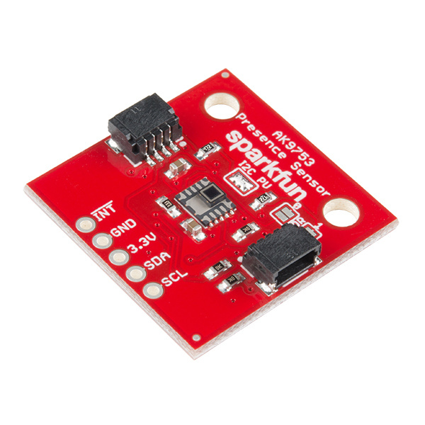
The AK9753 Human Presence sensor is a Qwiic enabled, 4-channel Nondispersive Infrared Sensor (NDIR). Each channel has a different field of view, so not only can the AK9753 detect a human, but it can also tell which direction the person is moving.
This hookup guide will show you how to get started taking basic reading from the sensor. We will cover both a serial output of readings as well as nice graph of the derivative of our readings from a single channel.
Required Materials
To get started, you'll need a microcontroller to, well, control everything.

Particle Photon (Headers)
WRL-13774
Raspberry Pi 3
DEV-13825Now to get into the Qwiic ecosystem, the key will be one of the following Qwiic shields to match your preference of microcontroller:

SparkFun Qwiic Shield for Photon
DEV-14477You will also need a Qwiic cable to connect the shield to your human presence sensor, choose a length that suits your needs.

Qwiic Cable - 50mm
PRT-14426
Qwiic Cable - 100mm
PRT-14427
Qwiic Cable - 200mm
PRT-14428
Qwiic Cable - 500mm
PRT-14429Suggested Reading
If you aren't familiar with the Qwiic system, we recommend reading here for an overview.
| Qwiic Connect System |
We would also recommend taking a look at the following tutorials if you aren't familiar with them.
I2C
Qwiic Shield for Arduino & Photon Hookup Guide
Hardware Overview
Listed below are some of the characteristics and operating ranges of the AK9753 Human Presence Sensor.
| Characteristic | Range |
|---|---|
| Operating Voltage | 3.3V |
| Operating Temperature | -30°C to 85°C |
| Current Consumption | 10 μA (typ.), 100 μA (max) (5V) |
| Spectral Sensitivity | 5-7 μm (5V) |
| Detection Range | 3 m (5V) |
| Temperature Sensor Range | -10° to 60°C |
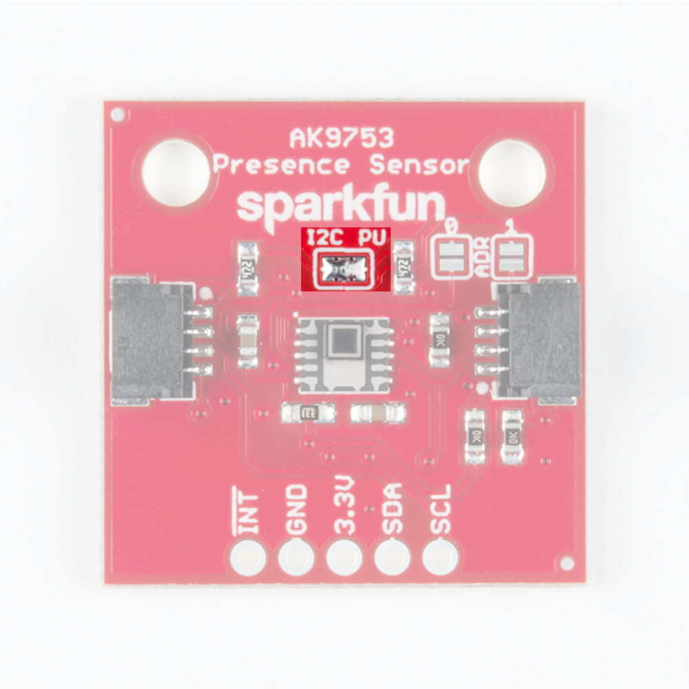
Pins
| Pin | Description | Direction |
|---|---|---|
| GND | Ground | In |
| 3.3V | Power | In |
| SDA | Data | In |
| SCL | Clock | In |
| INT | Interrupt, goes high when data is ready. After data is read, the pin pulls low | Out |
Optional Features
There are several jumpers on board that can be changed to facilitate several different functions. The first of which is the I2C pull-up jumper, highlighted below. If multiple sensors are connected to the I2C bus with the pull-up resistors enabled, the parallel equivalent resistance will create too strong of a pull-up for the bus to operate correctly. As a general rule of thumb, disable all but one pair of pull-up resistors if multiple devices are connected to the bus. If you need to disconnect the pull up resistors they can be removed by removing the solder from this jumper.
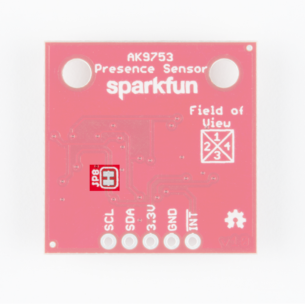
The JP8 jumper on the back of the board (highlighted below) can be sliced with a hobby knife to disable the interrupt capability. The "Field of View" text and box shows the field of view of each of the 4 sensors. From the sensor's point of view, channel 1 is on top, 2 is on left, 3 is on bottom, and 4 is on the right.
Addresses 0 and 1 can be used to change the I2C address of the board in case you have multiple devices using the same address. The below table shows the addresses that correspond to the different combinations of opened and closed jumpers.

| Address 0 | Address 1 | I2C Address |
|---|---|---|
| 0 | 0 | 0x64 |
| 0 | 1 | 0x65 |
| 1 | 0 | 0x67 |
| 1 | 1 | Switch Mode |
Switch mode is available if you want to avoid using I2C altogether. In switch mode, data is written to the interrupt pin. The pin pulls high when the difference between two outputs (ex. IR1-IR3 or IR2-IR4) is greater than the upper or lower thresholds set in EEPROM by the manufacturer. This mode is a good solution if your project doesn't need much accuracy.
Hardware Assembly
If you haven't yet assembled your Qwiic Shield, now would be the time to head over to that tutorial. With the shield assembled, Sparkfun's new Qwiic environment means that connecting the sensor could not be easier. Just plug one end of the Qwiic cable into the AK9753 Human Presence Sensor, the other into the Qwiic Shield and you'll be ready to upload a sketch and start sensing humans. It seems too easy, but thats why we made it this way!
Example Code
Note: This example assumes you are using the latest version of the Arduino IDE on your desktop. If this is your first time using Arduino, please review our tutorial on installing the Arduino IDE. If you have not previously installed an Arduino library, please check out our installation guide.
First, you'll need to download and install the SparkFun AK975X Arduino library, this can be done using the button below or by using the Arduino Library Manager.
Before we get started developing a sketch, let's look at the available functions of the library.
int16_t getIR1();--- Returns the value from channel 1, there are also functionsgetIR2();and so on and so forth.void refresh();--- Reads the dummy register telling the sensor to calculate the next reading.boolean available();--- Returnstrueif data is ready.boolean overrun();--- Returns true if the overrun bit is set.void softReset();--- Resets the IC via software.void setMode(uint8_t mode = AK975X_MODE_0);--- Set mode of the sensor. Mode 0 is continuous read mode.void setCutoffFrequency(uint8_t frequency = AK975X_FREQ_8_8HZ);--- Sets the filtering frequency. 8Hz is the fastest and least filtered.float getTemperature();--- Returns sensor temperature in °C.float getTemperatureF();--- Returns sensor temperature in °F.void enableDebugging(Stream &debugPort = Serial);--- Self explanatory, allows the output various extra messages to help with debugging.void disableDebugging();--- Disables debugging messages.uint8_t readRegister(uint8_t location);--- Basic read of I2C register.void writeRegister(uint8_t location, uint8_t val);--- Writes to an I2C register.uint16_t readRegister16(byte location);--- Reads a 16-bit value from an I2C register.
Example 1: Basic Serial Readings
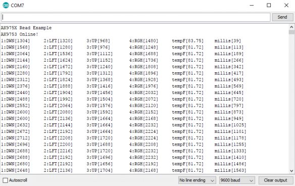
The example code shown below will get you started taking basic serial readings from the Human Presence Sensor. This sketch is relatively simple, pulling values using the getIRX(); functions and printing them over a serial terminal at 9600 baud.
language:c
#include <Wire.h>

#include "SparkFun_AK975X_Arduino_Library.h" //Use Library Manager or download here: https://github.com/sparkfun/SparkFun_AK975X_Arduino_Library

AK975X movementSensor; //Hook object to the library

int ir1, ir2, ir3, ir4, temperature;

void setup()
{
  Serial.begin(9600);
  Serial.println("AK975X Read Example");

  Wire.begin();

  //Turn on sensor
  if (movementSensor.begin() == false)
  {
    Serial.println("Device not found. Check wiring.");
    while (1);
  }
}

void loop()
{
  if (movementSensor.available())
  {
    ir1 = movementSensor.getIR1();
    ir2 = movementSensor.getIR2();
    ir3 = movementSensor.getIR3();
    ir4 = movementSensor.getIR4();
    float tempF = movementSensor.getTemperatureF();

    movementSensor.refresh(); //Read dummy register after new data is read

    //Note: The observable area is shown in the silkscreen.
    //If sensor 2 increases first, the human is on the left
    Serial.print("1:DWN[");
    Serial.print(ir1);
    Serial.print("]\t2:LFT[");
    Serial.print(ir2);
    Serial.print("]\t3:UP[");
    Serial.print(ir3);
    Serial.print("]\t4:RGH[");
    Serial.print(ir4);
    Serial.print("]\ttempF[");
    Serial.print(tempF);
    Serial.print("]\tmillis[");
    Serial.print(millis());
    Serial.print("]");
    Serial.println();
  }
  delay(1);
}
The output should look similar to the image below, with the values of each channel, temperature, and timestamp of the reading in each row.
Example 2: Graphing the Human Presence Sensor Serial Data
The next example takes the derivative of a single channel and displays this on the serial plotter. The code for this example is shown below. Notice how you can change the sensitivity of the Human Presence Sensor using the sensitivity value. It is set at 50 by default, and values lower than this will yield higher sensitivity.
language:c
#include <Wire.h>

#include "SparkFun_AK975X_Arduino_Library.h" //Use Library Manager or download here: https://github.com/sparkfun/SparkFun_AK975X_Arduino_Library

AK975X movementSensor; //Hook object to the library

unsigned int upValue; // current proximity reading
unsigned int averageValue;   // low-pass filtered proximity reading
signed int fa2;              // FA-II value;
signed int fa2Derivative;     // Derivative of the FA-II value;
signed int fa2DerivativeLast;     // Last value of the derivative (for zero-crossing detection)
signed int sensitivity = 50;  // Sensitivity of touch/release detection, values closer to zero increase sensitivity

#define LOOP_TIME 30  // Loop duration in ms. 30ms works well.

//Exponential average weight parameter / cut-off frequency for high-pass filter
//#define EA 0.3  //Very steep
//#define EA 0.1  //Less steep
#define EA 0.05  //Less steep

void setup()
{
  Serial.begin(9600);

  Wire.begin();

  //Turn on sensor
  if (movementSensor.begin() == false)
  {
    Serial.println("Device not found. Check wiring.");
    while (1);
  }

  upValue = movementSensor.getIR3(); //Get one of the latest IR values
  averageValue = upValue;
  fa2 = 0;
  movementSensor.refresh(); //Read dummy register after new data is read
}

void loop()
{
  unsigned long startTime = millis();

  while (movementSensor.available() == false) delay(1); //Wait for new data

  upValue = movementSensor.getIR3(); //Get one of the latest IR values
  movementSensor.refresh(); //Read dummy register after new data is read

  fa2DerivativeLast = fa2Derivative;
  fa2Derivative = (signed int) averageValue - upValue - fa2;
  fa2 = (signed int) averageValue - upValue;

  //Turn on various variables to see how they respond on the graph
  //Serial.print(upValue);
  //Serial.print(",");
  //Serial.print(fa2);
  //Serial.print(",");
  Serial.print(fa2Derivative);
  Serial.print(",");

  //Look to see if the previous fa2Der was below threshold AND current fa2Der is above threshold
  //Basically, if the sign of the fa2Ders has switched since last reading then we have an event
  if ((fa2DerivativeLast < -sensitivity && fa2Derivative > sensitivity) || (fa2DerivativeLast > sensitivity && fa2Derivative < -sensitivity)) // zero crossing detected
  {
    if (fa2 < -sensitivity) // minimum
    {
      Serial.print(-1000); //Cause red line to indicate entering presence
      Serial.print(",");
      //Serial.print("Entered view");
    }
    else if (fa2 > sensitivity) // maximum
    {
      Serial.print(1000); //Cause red line to indicate exiting presence
      Serial.print(",");
      //Serial.print("Exited view");
    }
    else
    {
      Serial.print(0); //Cause red line to indicate no movement
      Serial.print(",");
      //Serial.print("No Movement");
    }
  }
  else
  {
    Serial.print(0);
    Serial.print(",");
  }

  Serial.println();

  // Do this last
  averageValue = EA * upValue + (1 - EA) * averageValue;
  while (millis() < startTime + LOOP_TIME); // enforce constant loop time
}
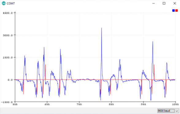
Once again, the output for this example code should look something like the below image. This graph is the derivative of a single channel on our presence sensor, so any variance from 0 shows the rate of change of the signal.
Example 3: Configuration Settings
The third example simply shows you how to set your AK9753 up on different addresses, baud rates, and I2C speeds. Simply call the non-default begin() function by including the arguments for wire port, I2C speed, I2C address and baud rate. For example, calling movementSensor.begin(Wire, I2C_SPEED_FAST, 0x64, 115200); will start the sensor with a fast I2C speed on address 0x64 with a baud of 115200 bps. Output of this example should look similar to Example 1.
Example 4: Threshold Tests
In this example, we'll go over how to set up the differential interrupt capabilities of the AK9753. To get started, go ahead and open up the example in File > Examples > SparkFun AK9750 Human Presence Sensor Library > Example4_ThresholdTests. Let's also connect the interrupt on our AK9753 to pin A3 on our Arduino, as this will read the status of the interrupt pin. Uploading this code to our Arduino and opening the Serial monitor to a baud of 115200 will open up a menu showing how to change the various settings related to interrupts. By sending Serial commands to our Arduino, we can change the interrupt characteristics around until they're just how we like them. The table of available Serial commands is shown below.
| Characteristic | Command (byte, [Range]) |
|---|---|
| High Threshold | 1, [-2048, 2048] |
| Low Threshold | 2, [-2048, 2048] |
| Hysteresis | 3, [0, 31] |
| Interrupt Enable | 4, [0, 31] |
| Read Interrupt Status | 5 |
| Begin Readings | 6 |
| Stop Readings | 7 |
For example, to set the high threshold, send the command 1,x where x is any number from -2048 to 2048. Play around with. The only place where sending Serial commands gets tricky is with the Interrupt Enable as we should be sending a binary value, but the Serial monitor is an ASCII interface, so we'll have to convert the binary for the interrupts we want to enable into decimal values. A chart to help you out is shown below. (IR13HI means the high threshold interrupt between 1 and 3, the H will be an L for the low threshold interrupts)
| Interrupt | Decimal Value |
|---|---|
| IR13HI | 16 |
| IR13LI | 8 |
| IR24HI | 4 |
| IR24LI | 2 |
| DATAREADY | 1 |
If you wanted to enable DATAREADY and IR13LI you would add 1 to 8 and send the command 4, 9 over Serial.
Resources and Going Further
Now that you've successfully got your AK9753 up and running, it's time to incorporate it into your own project!
For more information on the AK9753, check out the resources below:
- AK9753 Schematic (PDF)
- AK9753 Eagle Files (ZIP)
- AK9753 Datasheet (PDF)
- Product Showcase: Qwiic Presence Sensor
- Qwiic System Landing Page
- SparkFun AK975X Arduino Library GitHub Repository -- Source and example files for the Arduino library used in this tutorial.
- GitHub Repository - Repo for the product.
Need some inspiration for your next project? Check out some of these related tutorials: