OpenPIR Hookup Guide
Introduction
Passive Infrared (PIR) sensors detect motion in a local area and are the sensor of choice in security systems, home automation and proximity-sensing applications.
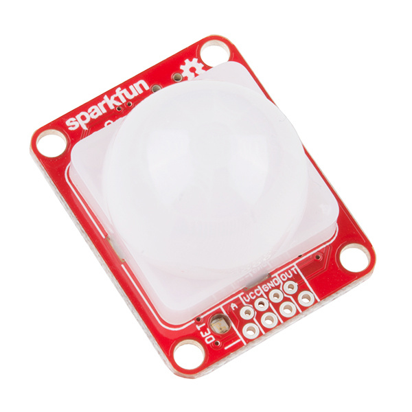
SparkFun OpenPIR
SEN-13968The SparkFun OpenPIR is a highly customizable PIR sensor based around the NCS36000 PIR controller. The OpenPIR allows you to set the sensitivity, trigger time and pulse mode of the motion sensor, so you can tailor-fit it to your application.
Required Materials
To follow along with this hookup guide, a handful of components are suggested in addition to the OpenPIR. A microcontroller development board, like an Arduino, RedBoard, Photon or Teensy is recommended. The development board can be used to both power the OpenPIR and act on its motion triggers.
Teensy 3.2
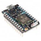
DEV-13736Particle Photon (Headers)
WRL-13774You'll also need something to electrically connect the OpenPIR's power and signal pins to that microcontroller. The OpenPIR includes both a 0.1" header and a 4-pin JST connector footprint, so you can use male headers or a 4-pin JST cable assembly to interface with the sensor.
Tools
Finally, you'll need soldering tools to electrically connect the connector of your choice to the OpenPIR. A simple soldering iron and solder should be all you need.
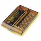
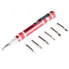
You may also need a small Phillips-head screwdriver to adjust the pair of trimpots on the back of the OpenPIR. Our pocket screwdriver includes a small enough bit, as does the larger screwdriver and bit set.
Suggested Reading
If you aren’t familiar with the following concepts, we recommend checking out these tutorials before continuing.
Analog to Digital Conversion
Logic Levels
Analog vs. Digital
PIR Motion Sensor Hookup Guide
Hardware Overview
Powering and interfacing with the OpenPIR is accomplished using the four pins broken out on the bottom of the board. Those pins are:
| Pin Label | Description |
|---|---|
| A | Analog output of NCS36000 differential amplifiers. |
| VCC | Power supply input |
| GND | Ground supply input |
| OUT | Digital output signal – active-high. |
More on those pins in the sections below.
Supplying Power
Power to the OpenPIR should be supplied to the VCC and GND pins. The OpenPIR's operating voltage supply range is 3V to 5.75V --- as specified by the board's NCS36000 PIR controller. That means it should work with any 3.3V or 5V system.
Electrical characteristics:
- Voltage supply range: 3VDC to 5.75VDC
- Standby average current: 80µA
- Motion-detected average current: 3mA (LED enabled)
The OpenPIR consumes relatively little power. When the sensor isn't triggered --- and the activity LED is not illuminated --- the OpenPIR will consume about 80µA. When active, the onboard LED's current draw dwarfs the PIR's operating current, consuming about 3mA. That LED can be disabled using the xLED jumper (see applicable section below).
Digital Motion Trigger Output
The OUT pin is an active-high digital signal, which indicates the OpenPIR's motion detection. When motion is detected, the pin is driven HIGH; otherwise it will be LOW.
This pin can drive up to 10mA --- so you can hook an LED or other small load up to it. Otherwise it can be connected directly to a microcontroller input pin (no pull-up or pull-down resistor required).
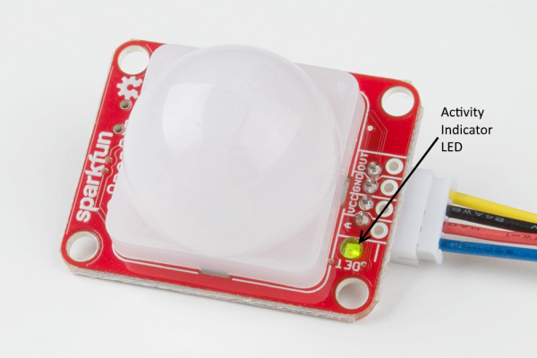
The operation of this pin is mirrored by the green, reverse-entry "DET"-labeled LED --- if the LED is on, the OUT pin should be HIGH.
The duration of a HIGH signal on the OUT pin is set by the "OSC" trimpot, which is discussed more in-depth later in this section.
Analog Output
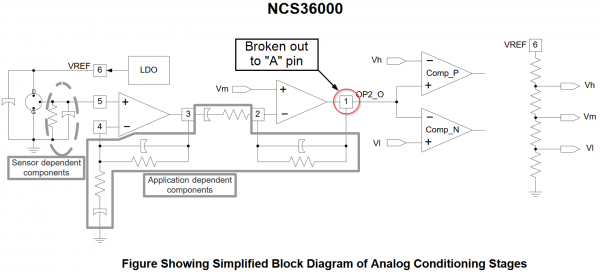
The "A"-labeled output breaks out the amplified PIR signal before it's sent to a window comparator, and then to the OUT pin.
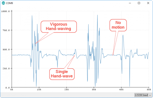
Absent of any motion, the voltage at this pin will hover around 2.1V (about 430 on a 5V Arduino's 10-bit ADC input). As motion is detected, though, that voltage may swing wildly.
This pin can be used to get a better idea of what kind of motion triggered the PIR. Single passes by the PIR may only produce a small "blip" on the "A" pin, while vigorous motion may produce a large, spiky wave output.
LED Output
A reverse-entry green LED is included on the board, which duplicates the status of the OUT pin. When motion is detected, the LED will illuminate; otherwise it will remain off.
On initial power-up, the LED will blink, indicating the NCS36000 is in start-up mode. Start-up mode can last for a few seconds or a couple of minutes --- the length of time spent in start-up depends on the position of the "OSC" trimpot. The start-up mode time upon shipment is about two minutes.
The LED can be disabled by opening the "xLED" jumper. Note that the LED will still blink during start-up mode, regardless of the jumper's state.
Trimpots --- Sensitivity and Oscillator Window
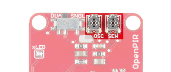
The pair of trimming potentiometers (trimpots) on the backside of the OpenPIR can be used to customize the behavior of your motion sensor.
The sensitivity trimpot --- labeled "SEN" --- can be used to adjust the view distance of the OpenPIR. The more clockwise you turn this trimpot, the further your sensor should be able to see. When you receive the board, the trimpot will be centered, and the sensor will react to a person moving about in the 6 to 8 foot (2 to 2.5m) range. At the maximum sensitivity, the sensor will detect a person walking by at about 16 feet (5m).
Avoid turning the "SEN" trimpot all the way down (counter-clockwise). This will disable the OpenPIR's output – even the most mobile environments will not trigger an active output.
The "OSC" trimpot ultimately controls the length of time the output remains HIGH. This trimpot is used to adjust the oscillator frequency of the NCS36000. Turning this trimpot clockwise increases the length of time OUT remains high.
With the OSC trimpot cranked all the way in the counterclockwise direction, the OUT pin will remain HIGH for about 400 milliseconds. Conversely, when the trimpot is turned to the far-clockwise, the OSC pin will remain HIGH for about 7.5 seconds. The trigger time should adjust relatively linearly between those two values. When you receive the board, it will be centered, and the trigger pulse will last a bit less than four seconds.
Trigger Mode --- Dual vs. Single
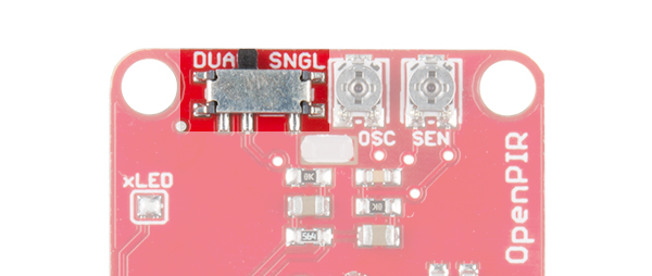
The NCS36000 supports two motion-detection modes: single-pulse and dual-pulse. Either of these modes can be selected using the switch adjacent to the trimpots on the back of the board.
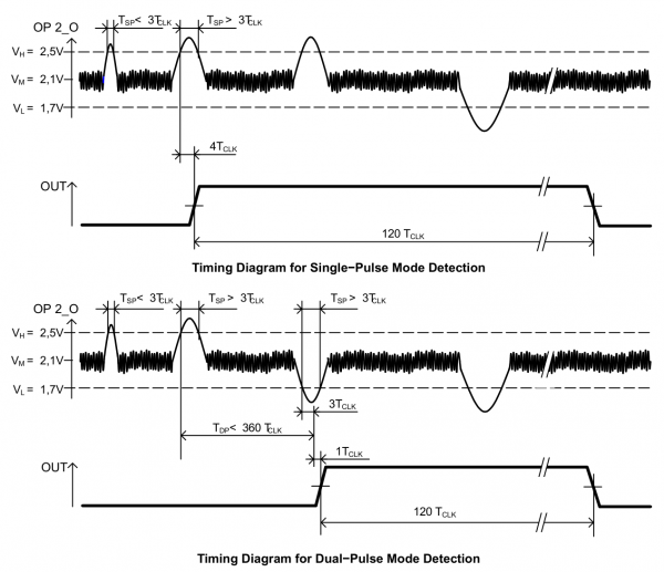
The NCS36000 uses a window comparator --- a pair of comparators with upper and lower voltage limits --- to trigger a pulse on the OUT pin. In single-pulse mode, a voltage above or below the upper or lower comparators will trigger an output pulse. But in dual-pulse mode, the voltage must swing above the high comparator voltage and below the low comparator voltage --- within a set time limit --- to trigger an output.
These timing diagrams from the NCS36000 datasheet can help to clarify single-pulse versus dual-pulse:
Single-pulse mode can be used to detect an object entering or exiting the PIR's field-of-view, while dual-pulse detection can be used to detect an object entering and leaving the view area.
Hardware Assembly
Before you can power the OpenPIR and connect it to a project, you'll need to solder something to the quartet of pins on the bottom of the board.
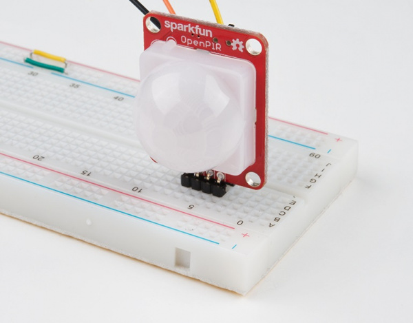
The OpenPIR's power and output pins are broken out to both a standard 0.1" header and a 4-pin JST PH connector, leaving you a number of options for what, exactly, you'll solder to the sensor. To the 0.1" header, you can solder male headers (or the right-angle version), female headers or wire.
Or you can solder a 4-Pin JST connector to the smaller-pitch footprint.
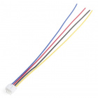
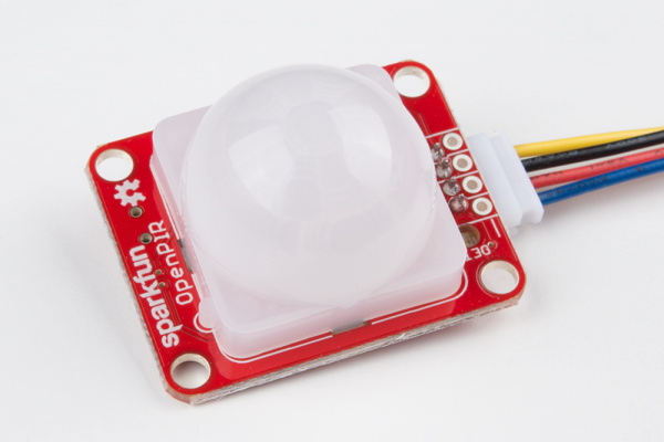
As a bonus, plugging our 4-wire JST cable assembly into the OpenPIR will logically color-code the power supply pins --- VCC on red, GND on black, OUT on yellow, and the analog output connected to blue.
Software
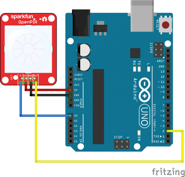
The firmware example below uses Arduino to demonstrate how both the digital output and analog output can be used. Here is the example circuit used in the example code:
Then upload the example code below so you can begin to get a feel for the OpenPIR's output pins:
language:c
//////////////////////////
// Hardware Definitions //
//////////////////////////
#define PIR_AOUT A0  // PIR analog output on A0
#define PIR_DOUT 2   // PIR digital output on D2
#define LED_PIN  13  // LED to illuminate on motion

#define PRINT_TIME 100 // Rate of serial printouts
unsigned long lastPrint = 0; // Keep track of last serial out

void setup()
{
  Serial.begin(115200);  // Serial is used to view Analog out
  // Analog and digital pins should both be set as inputs:
  pinMode(PIR_AOUT, INPUT);
  pinMode(PIR_DOUT, INPUT);

  // Configure the motion indicator LED pin as an output
  pinMode(LED_PIN, OUTPUT);
  digitalWrite(LED_PIN, LOW); // Turn the LED off
}

void loop()
{
  // Read OUT pin, and set onboard LED to mirror output
  readDigitalValue();

  // Read A pin, print that value to serial port:
  printAnalogValue();
}

void readDigitalValue()
{
  // The OpenPIR's digital output is active high
  int motionStatus = digitalRead(PIR_DOUT);

  // If motion is detected, turn the onboard LED on:
  if (motionStatus == HIGH)
    digitalWrite(LED_PIN, HIGH);
  else // Otherwise turn the LED off:
    digitalWrite(LED_PIN, LOW);
}

void printAnalogValue()
{
  if ( (lastPrint + PRINT_TIME) < millis() )
  {
    lastPrint = millis();
    // Read in analog value:
    unsigned int analogPIR = analogRead(PIR_AOUT);
    // Convert 10-bit analog value to a voltage
    // (Assume high voltage is 5.0V.)
    float voltage = (float) analogPIR / 1024.0 * 5.0;
    // Print the reading from the digital pin.
    // Mutliply by 5 to maintain scale with AOUT.
    Serial.print(5 * digitalRead(PIR_DOUT));
    Serial.print(',');    // Print a comma
    Serial.print(2.5);    // Print the upper limit
    Serial.print(',');    // Print a comma
    Serial.print(1.7);    // Print the lower limit
    Serial.print(',');    // Print a comma
    Serial.print(voltage); // Print voltage
    Serial.println();
  }
}
This code uses the Arduino's onboard LED --- on pin 13 --- to reflect the OpenPIR's digital motion output. When motion is detected, the Arduino's LED should illuminate.
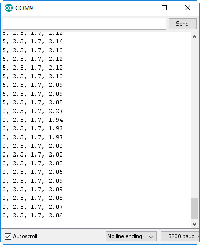
Four values are printed to the serial terminal --- the reading from the digital pin (multiplied by 5...for a reason), the upper and lower comparator voltage thresholds and the reading from the analog pin. Open up your serial monitor --- setting the baud rate to 115200 --- to see them stream by:
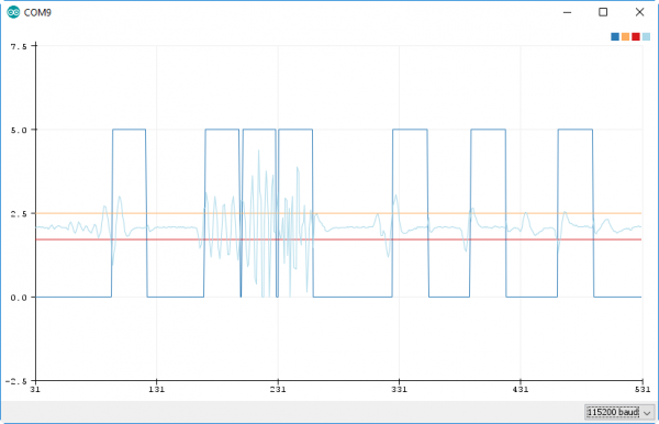
Since it may be difficult to visualize the sensor's analog output using the serial terminal, try opening up the serial plotter (found under the "Tools" > "Serial Plotter" menu).
You should see two separate line graphs: the light blue indicating the analog value and the dark blue representing the digital output. The orange and red straight lines represent the upper and lower thresholds, which the analog value must exceed to trigger motion.
Wave at the sensor to get a better feel for the analog output's behavior. And make sure you try both single and dual modes to see how the switch alters the sensor's functionality.
Resources & Going Further
Now that you’ve successfully got your OpenPIR up and running, it’s time to incorporate it into your own project!
For more information, check out the resources below:
Need some inspiration for your next project? Check out some of these related tutorials:
