What time is it? Time for you to... Qwiic-ly build a GPS clock and output it to a display! This project provides you with the current date and time using GPS satellites. Depending on your display, you can draw the time as a digital or analog clock. Or even configure the clock to read military time, adjust the clock for your time zone, or automatically adjust the time for daylight savings time!
If you aren't familiar with the Qwiic system, we recommend reading here for an overview.
| Qwiic Connect System |
We also recommend checking out these tutorials before continuing. You may also need to read additional tutorials related with your choice of display. The DST code is based on Nate's Alphanumeric GPS all Clock project.
The following code used in this tutorial has been written and tested on Arduino IDE version 1.8.12. Otherwise, make sure you are using the latest stable version of the Arduino IDE on your desktop. You can find a list of stable versions on Arduino's site. If this is your first time using Arduino, please review our tutorial on installing the Arduino IDE.
If you have not previously installed an Arduino library, please check out our installation guide to automatically install.
At a minimum, you will need the u-blox Arduino library. The following code is based on example 15. Additional code was added to adjust the date and time based on:
The SparkFun U-blox Arduino library can be downloaded with the Arduino library manager by searching 'SparkFun Ublox' or you can grab the zip here from the GitHub repository. At the time of writing this tutorial, we were using version 1.8.5.
Depending on the display that you use, you may need additional library installed. You will need to check out the hookup guide for the display for more information.
Depending on your board, you may need to install drivers to upload code to the Arduino. In this case, we'll be using the RedBoard Qwiic with the CH340 populated on the board. They should automatically be installed on your computer. However, if you need to manually install the drivers, check out the following tutorial.
If you are using a different development board, you may need to install a different driver. Some have dedicated ICs like the FTDI but others may have a built-in CDC for the COM port (i.e. ATmega32U4, SAMD21, SAMD51, etc.). You will need to check out the hookup guide for that board for more information.
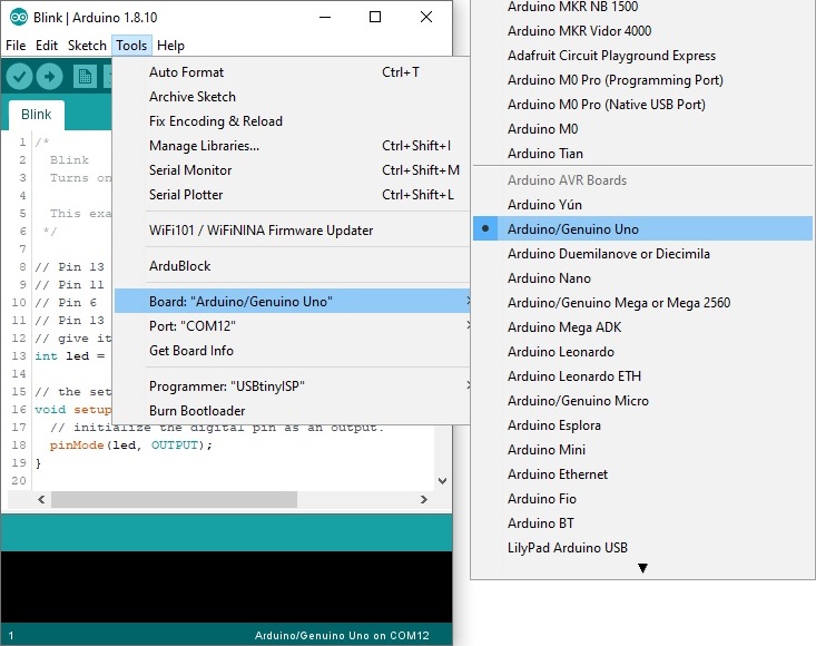
Since we are using the RedBoard Qwiic, we do not need to install a board in the Arduino IDE as it is using the Arduino Uno for the board selection. If you decide to use a different board, you may need to install additional dependencies for that processor. You will need to check out the board's hookup guide for more information as well.
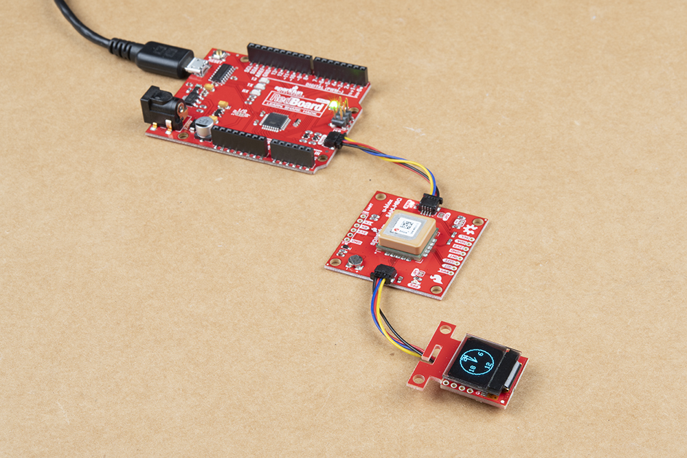
This Arduino example is for the minimalist. All you need is a microcontroller and a Qwiic-enabled GPS to view the date and time in your region via a computer. This will be a template for the subsequent examples.
For each serial output, you'll simply adjust the code as necessary for your preferred display. This can range from LCDs, OLEDs, LED RGB matrices, rows of addressable LED strips, 7-segment LEDs, and alphanumeric LEDs. Depending on your display, you'll need to be careful about the size of your code, how much RAM you are using, and power consumption. We will provide examples for a few displays in this tutorial.
To follow along with this example, you will need the following materials. You may not need everything though depending on what you have. Add it to your cart, read through the guide, and adjust the cart as necessary.
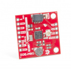
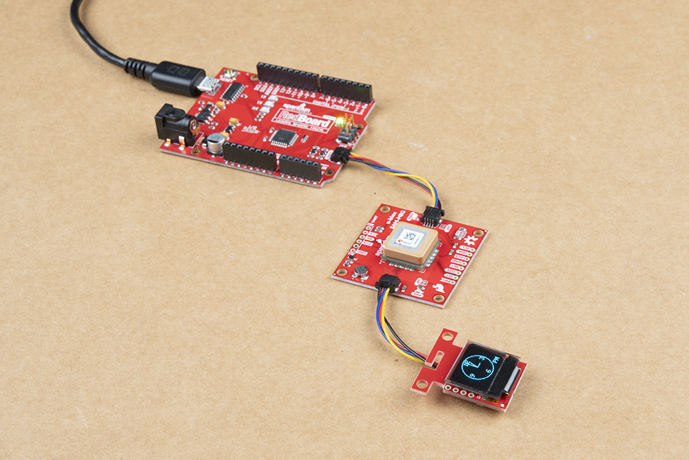
Connecting the boards together is easy. Simply add a Qwiic cable between your Arduino and u-blox GPS module. In this case, we used the RedBoard Qwiic with ATmega328P and Qwiic GPS breakout with SAM-M8Q. Depending on your personal preference, you'll want to adjust the code to view on your display.
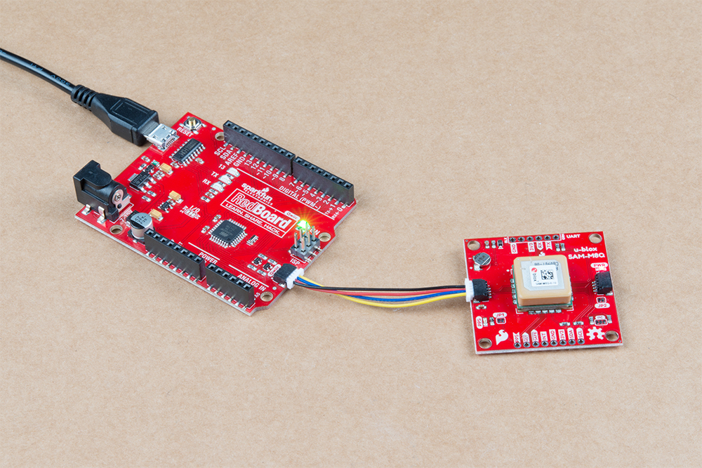
Copy and paste the code in the Arduino IDE. Select the board (in this case the Arduino Uno) and COM port that it enumerated to. Hit the upload button.
language:c
/*
Getting the time and date in your timezone using Ublox commands
Originally Written By: davidallenmann
Modified By: Ho Yun "Bobby" Chan
SparkFun Electronics
Date: April 16th, 2019
License: MIT. See license file for more information but you can
basically do whatever you want with this code.
This is a modified example that shows how to query a Ublox module for the current time and date. We also
turn off the NMEA output on the I2C port. This decreases the amount of I2C traffic
dramatically.
Leave NMEA parsing behind. Now you can simply ask the module for the datums you want!
Additionally, this code has the option to adjust the UTC date and time. The time is adjusted by manually
entering your time zone's offset. The Daylight Savings Time is automatically calculated with the help of
Nathan Seidle's Daylight Savings Time example [ https://github.com/nseidle/Daylight_Savings_Time_Example ].
However, if your country does not observe DST, you can override it with the `enableDST` variable.
The output for this example is sent through a Serial UART port. Depending on personal preference, you can view
the time in regular 12-hour format or miltary 24-hour format.
Feel like supporting open source hardware?
Buy a board from SparkFun!
ZED-F9P RTK2: https://www.sparkfun.com/products/15136
NEO-M8P RTK: https://www.sparkfun.com/products/15005
SAM-M8Q: https://www.sparkfun.com/products/15106
Hardware Connections:
Plug a Qwiic cable into the u-Blox Qwiic-enabled GPS and the RedBoard Qwiic.
If you don't have a platform with a Qwiic connection use the SparkFun Qwiic Breadboard Jumper (https://www.sparkfun.com/products/14425)
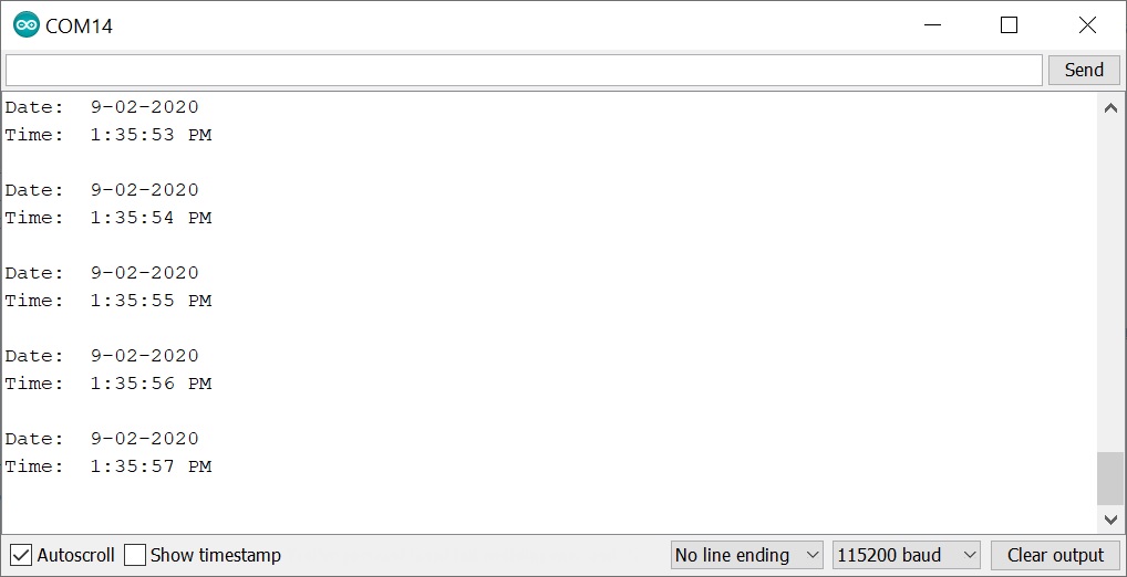
Open the serial monitor at 115200 baud to see the output.
*/
#include <Wire.h> //Needed for I2C to GPS
#include "SparkFun_Ublox_Arduino_Library.h" //http://librarymanager/All#SparkFun_Ublox_GPS
SFE_UBLOX_GPS myGPS;
long lastTime = 0; //Simple local timer. Limits amount if I2C traffic to Ublox module.
long latitude = 0;
long longitude = 0;
long altitude = 0;
byte SIV = 0;
boolean DST = false; //adjust for Daylight Savings Time, this is calculated automatically. fall back = FALSE, spring forward = TRUE
boolean enableDST = true; //option to disable DST if your country does not observe DST
int zoneOffsetHour = -7; //adjust according to your standard time zone
byte DoW = 0; //needed to adjust hour for DST, or if you want to know the Day of the Week
boolean military = false; //adjust for miltary or AM/PM
boolean AM = false; //AM or PM?
// Use these variables to set the initial time: 3:03:00
int hours = 3;
int minutes = 3;
int seconds = 0;
//Tid Bit: https://www.sparkfun.com/news/2571#yearOrigin
int years = 2003; //year that SparkFun was founded!
int months = 1; //month that SparkFun was founded!
int days = 3; //day that SparkFun was founded!
// How fast do you want the clock to update? Set this to 1 for fun.
// Set this to 1000 to get _about_ 1 second timing.
const int CLOCK_SPEED = 1000;
unsigned long lastDraw = 0;
void setup(){
Serial.begin(115200);
//while (!Serial)
// ; //Wait for user to open terminal
Serial.println(F("SparkFun Ublox Example"));
Wire.begin();
Wire.setClock(400000); // Set clock speed to be the fastest for better communication (fast mode)
if (myGPS.begin() == false) //Connect to the Ublox module using Wire port
{
Serial.println(F("Ublox GPS not detected at default I2C address. Please check wiring. Freezing."));
while (1)
;
}
myGPS.setI2COutput(COM_TYPE_UBX); //Set the I2C port to output UBX only (turn off NMEA noise)
myGPS.saveConfiguration(); //Save the current settings to flash and BBR
}//end setup()
void loop(){
update_Time(); //adjust UTC date/time based on time zone and DST
displayDigital_Date_Time(); //after calculating, display the date and time
} //end loop
// Simple function to increment seconds and then increment minutes
// and hours if necessary.
void update_Time() {
//Query module only every second. Doing it more often will just cause I2C traffic.
//The module only responds when a new position is available
if (millis() - lastTime > 1000) {
lastTime = millis(); //Update the timer
latitude = myGPS.getLatitude();
longitude = myGPS.getLongitude();
altitude = myGPS.getAltitude();
SIV = myGPS.getSIV();
years = myGPS.getYear();
months = myGPS.getMonth();
days = myGPS.getDay();
hours = myGPS.getHour();
minutes = myGPS.getMinute();
seconds = myGPS.getSecond();
calcZone_DST(); //adjust zone and used to check if it is Daylight Savings Time
}
//Serial.print(F("Lat: "));
//Serial.print(latitude);
//Serial.print(F(" Long: "));
//Serial.print(longitude);
//Serial.print(F(" (degrees * 10^-7)"));
//Serial.print(F(" Alt: "));
//Serial.print(altitude);
//Serial.print(F(" (mm)"));
//Serial.print(F(" SIV: "));
//Serial.print(SIV);
//Serial.println();
}
//Nate's snazzy code!
//Given a year/month/day/current UTC/local offset give me local time
void calcZone_DST() {
//Since 2007 DST starts on the second Sunday in March and ends the first Sunday of November
//Let's just assume it's going to be this way for awhile (silly US government!)
//Example from: http://stackoverflow.com/questions/5590429/calculating-daylight-savings-time-from-only-date
DoW = day_of_week(); //Get the day of the week. 0 = Sunday, 6 = Saturday
int previousSunday = days - DoW;
//DST = false; //Assume we're not in DST
if (enableDST == true) {
if (months > 3 && months < 11) DST = true; //DST is happening!
//In March, we are DST if our previous Sunday was on or after the 8th.
if (months == 3)
{
if (previousSunday >= 8) DST = true;
}
//In November we must be before the first Sunday to be DST.
//That means the previous Sunday must be before the 1st.
if (months == 11)
{
if (previousSunday <= 0) DST = true;
}
}
//adjust time for DST here if it applies to your region
if (DST == true) {//adjust time Daylight Savings Time
hours = hours + 1;
}
else { //leave time as is for Daylight Time
}
//adjust time based on Time Zone
hours = hours + zoneOffsetHour;
//adjust for offset zones when hour is negative value
if (hours < 0) {
days = days - 1;
hours = hours + 24;
}
else if ( hours > 23) {
days = days + 1;
hours = hours - 24;
}
//adjust for AM/PM mode
if (military == false) {
if (hours >= 0 && hours <= 11) {// we are in AM
if (hours == 0) {
hours = 12;
}
AM = true;
}
else { // hours >= 12 && hours <= 23, therefore we are in PM!!!
if (hours > 12 && hours <= 23) {
hours = hours - 12;
}
AM = false;
}
}
/*
Serial.print("Hour: ");
Serial.println(hour);
Serial.print("Day of week: ");
if(DoW == 0) Serial.println("Sunday");
if(DoW == 1) Serial.println("Monday");
if(DoW == 2) Serial.println("Tuesday");
if(DoW == 3) Serial.println("Wednesday");
if(DoW == 4) Serial.println("Thursday");
if(DoW == 5) Serial.println("Friday!");
if(DoW == 6) Serial.println("Saturday");
*/
}
//Given the current year/month/day
//Returns 0 (Sunday) through 6 (Saturday) for the day of the week
//From: http://en.wikipedia.org/wiki/Calculating_the_day_of_the_week
//This function assumes the month from the caller is 1-12
char day_of_week() {
//Devised by Tomohiko Sakamoto in 1993, it is accurate for any Gregorian date:
static int t[] = { 0, 3, 2, 5, 0, 3, 5, 1, 4, 6, 2, 4 };
years -= months < 3;
return (years + years / 4 - years / 100 + years / 400 + t[months - 1] + days) % 7;
}
void displayDigital_Date_Time() {
if (lastDraw + CLOCK_SPEED < millis())
{
lastDraw = millis();
Serial.print(F("Date: "));
if (months <= 9) {
Serial.print(F(" "));
}
Serial.print(String(months) + '-');
if (days <= 9) {
Serial.print(F("0"));
}
Serial.println(String(days) + '-' + String(years));
Serial.print(F("Time: "));
if (hours <= 9) {
Serial.print(' ');
}
Serial.print(String(hours) + ':' );
if (minutes <= 9) {
Serial.print(F("0"));
}
Serial.print(String(minutes) + ':');
if (seconds <= 9) {
Serial.print(F("0"));
}
Serial.print(String(seconds));
if (military == false) {
if (AM == true) {
Serial.println(F(" AM"));
}
else {
if (AM == false) {
Serial.println(F(" PM"));
}
}
}
else {
Serial.println(); //space between military time for Serial Monitor
}
if (myGPS.getDateValid() == false) {
Serial.println(F("Date is invalid, not enough satellites in view!"));
}
if (myGPS.getTimeValid() == false) {
Serial.println(F("Time is invalid, not enough satellites in view!"));
}
Serial.println();
}
}
Open the Arduino Serial Monitor and set it to 115200 baud. You should start seeing the date and time. By default, the code will display the digital time in Mountain Time in 12-hour mode. Note that the date and time might not be current until enough satellites are in view. Depending on the day of the year, it will adjust the hour as necessary based on the day.
If you live in a different time zone, simply adjust the offset for your region (e.g. zoneOffsetHour) at the top of the code. If you don't live in a region which follows daylight savings time (DST), just adjust the boolean variable to override the calculation by setting the variable enableDST to false. You will also need to adjust the condition statements at the beginning of the calcZone_DST() function since the DST starts/ends on different days of the month. If you are interested in viewing the time in 24-hour, military format, just adjust the boolean variable military to true.
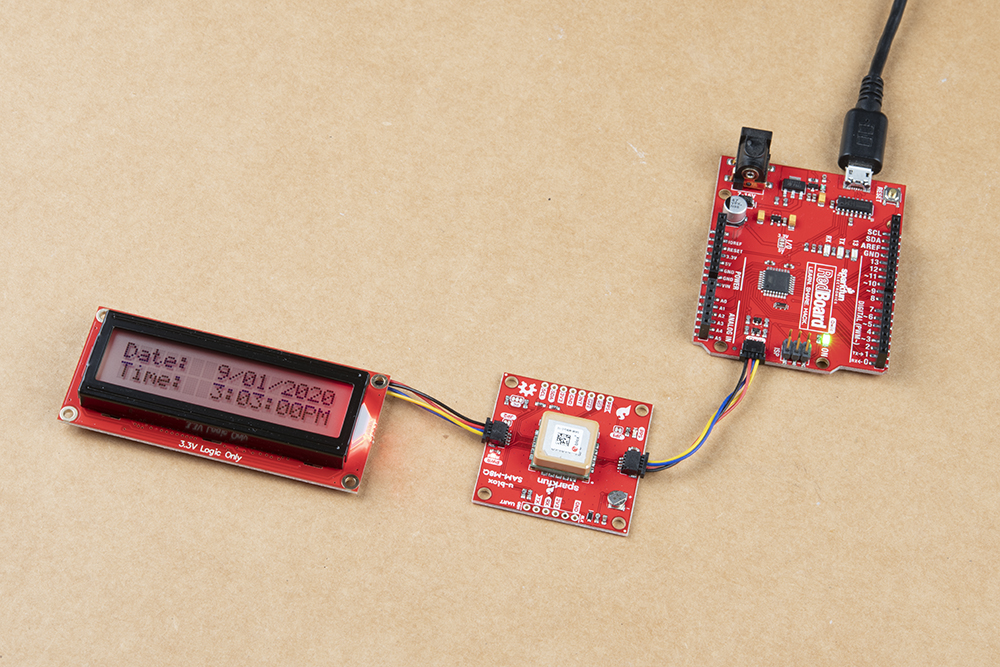
Based on the template, the following code is adjusted for the Qwiic SerLCD. The only difference is that we need to send a command or write data via I2C by each Serial.print() statement. Before and after each stream of data, we'll also need to open and close the I2C bus for each transmission.
To follow along with this example, you will need the following materials. You may not need everything though depending on what you have. Add it to your cart, read through the guide, and adjust the cart as necessary.
If you decide to use the SerLCD, we recommend taking a look at the following tutorial as well.
Connecting the boards together is easy. As opposed to using several wires with a basic character LCD screen like the examples in the SparkFun Inventor's Kit, the SerLCD reduces the number of wires down to four with the Qwiic system. Another advantage is that the Qwiic system uses a polarized connector so that you do not have to manually wire the LCD to the Arduino. Simply add a Qwiic cable between your Arduino, u-blox GPS module, and the display of your choice. In this case, we used the RedBoard Qwiic with ATmega328P, Qwiic GPS breakout with SAM-M8Q, and Qwiic SerLCD.
Copy and paste the code in the Arduino IDE. Select the board (in this case the Arduino Uno) and COM port that it enumerated to. Hit the upload button.
language:c
/*
  Getting the time and date in your timezone using Ublox commands
  Originally Written By: davidallenmann
  Modified By: Ho Yun "Bobby" Chan
  SparkFun Electronics
  Date: April 16th, 2019
  License: MIT. See license file for more information but you can
  basically do whatever you want with this code.

  This is a modified example that shows how to query a Ublox module for the current time and date. We also
  turn off the NMEA output on the I2C port. This decreases the amount of I2C traffic
  dramatically.

  Leave NMEA parsing behind. Now you can simply ask the module for the datums you want!

  Additionally, this code has the option to adjust the UTC date and time. The time is adjusted by manually
  entering your time zone's offset. The Daylight Savings Time is automatically calculated with the help of
  Nathan Seidle's Daylight Savings Time example [ https://github.com/nseidle/Daylight_Savings_Time_Example ].
  However, if your country does not observe DST, you can override it with the `enableDST` variable.

  The output on the Qwiic SerLCD is just digital. Depending on personal preference, you can view
  the time in regular 12-hour format or miltary 24-hour format.

  Feel like supporting open source hardware?
  Buy a board from SparkFun!
  ZED-F9P RTK2: https://www.sparkfun.com/products/15136
  NEO-M8P RTK: https://www.sparkfun.com/products/15005
  SAM-M8Q: https://www.sparkfun.com/products/15106

  Hardware Connections:
  Plug a Qwiic cable into the GPS, Qwiic SerLCD, and the RedBoard Qwiic.
  If you don't have a platform with a Qwiic connection use the SparkFun Qwiic Breadboard Jumper (https://www.sparkfun.com/products/14425)
  Open the serial monitor at 115200 baud to see the output.
*/

#include <Wire.h> //Needed for I2C to GPS
#include "SparkFun_Ublox_Arduino_Library.h" //http://librarymanager/All#SparkFun_Ublox_GPS
#define SerLCD_Address 0x72  //If using SerLCD with I2C

SFE_UBLOX_GPS myGPS;

long lastTime = 0; //Simple local timer. Limits amount if I2C traffic to Ublox module.
long latitude = 0;
long longitude = 0;
long altitude = 0;
byte SIV = 0;

boolean DST = false; //adjust for Daylight Savings Time, this is calculated automatically. fall back = FALSE, spring forward = TRUE
boolean enableDST = true; //option to disable DST if your country does not observe DST
int zoneOffsetHour = -7; //adjust according to your standard time zone
byte DoW = 0; //needed to adjust hour for DST, or if you want to know the Day of the Week
boolean military = false; //adjust for miltary (24-hr mode) or AM/PM (12-hr mode)
boolean AM = false; //AM or PM?

// Use these variables to set the initial time: 3:03:00
int hours = 3;
int minutes = 3;
int seconds = 0;

//Tid Bit: https://www.sparkfun.com/news/2571#yearOrigin
int years = 2020; //year that SparkFun was founded!
int months = 9;  //month that SparkFun was founded!
int days = 1;    //day that SparkFun was founded!

// How fast do you want the clock to update? Set this to 1 for fun.
// Set this to 1000 to get _about_ 1 second timing.
const int CLOCK_SPEED = 1000;
unsigned long lastDraw = 0;


void setup() {
  Serial.begin(115200);
  //while (!Serial)
  //  ; //Wait for user to open terminal
  Serial.println("SparkFun Ublox Example");

  Wire.begin();
  Wire.setClock(400000);   // Set clock speed to be the fastest for better communication (fast mode)


  if (myGPS.begin() == false) //Connect to the Ublox module using Wire port
  {
    Serial.println(F("Ublox GPS not detected at default I2C address. Please check wiring. Freezing."));
    while (1)
      ;
  }

  myGPS.setI2COutput(COM_TYPE_UBX); //Set the I2C port to output UBX only (turn off NMEA noise)
  myGPS.saveConfiguration();        //Save the current settings to flash and BBR

  Wire.beginTransmission(SerLCD_Address);
  Wire.write('|'); //Put LCD into setting mode
  Wire.write('-'); //Send clear display command

  Wire.write('|'); //Put LCD into setting mode
  Wire.write('+'); //Send the Set RGB command
  Wire.write(0xFF); //Send the red value
  Wire.write(0x00); //Send the green value
  Wire.write(0x00); //Send the blue value
  Wire.endTransmission();

}//end setup()


void loop() {

  update_Time();   //adjust UTC date/time based on time zone and DST

  displayDigital_Date_Time();  //after calculating, display the date and time on the SerLCD

} //end loop


// Simple function to increment seconds and then increment minutes
// and hours if necessary.
void update_Time() {

  //Query module only every second. Doing it more often will just cause I2C traffic.
  //The module only responds when a new position is available
  if (millis() - lastTime > 1000) {
    lastTime = millis(); //Update the timer

    latitude = myGPS.getLatitude();
    longitude = myGPS.getLongitude();
    altitude = myGPS.getAltitude();
    SIV = myGPS.getSIV();

    years = myGPS.getYear();
    months = myGPS.getMonth();
    days = myGPS.getDay();
    hours = myGPS.getHour();
    minutes = myGPS.getMinute();
    seconds = myGPS.getSecond();

    calcZone_DST(); //adjust zone and used to check if it is Daylight Savings Time

  }
  //Serial.print(F("Lat: "));
  //Serial.print(latitude);


  //Serial.print(F(" Long: "));
  //Serial.print(longitude);
  //Serial.print(F(" (degrees * 10^-7)"));


  //Serial.print(F(" Alt: "));
  //Serial.print(altitude);
  //Serial.print(F(" (mm)"));


  //Serial.print(F(" SIV: "));
  //Serial.print(SIV);

  //Serial.println();

}


//Nate's snazzy code!
//Given a year/month/day/current UTC/local offset give me local time
void calcZone_DST() {
  //Since 2007 DST starts on the second Sunday in March and ends the first Sunday of November
  //Let's just assume it's going to be this way for awhile (silly US government!)
  //Example from: http://stackoverflow.com/questions/5590429/calculating-daylight-savings-time-from-only-date

  DoW = day_of_week(); //Get the day of the week. 0 = Sunday, 6 = Saturday
  int previousSunday = days - DoW;

  //DST = false; //Assume we're not in DST
  if (enableDST == true) {
    if (months > 3 && months < 11) DST = true; //DST is happening!

    //In March, we are DST if our previous Sunday was on or after the 8th.
    if (months == 3)
    {
      if (previousSunday >= 8) DST = true;
    }
    //In November we must be before the first Sunday to be DST.
    //That means the previous Sunday must be before the 1st.
    if (months == 11)
    {
      if (previousSunday <= 0) DST = true;
    }
  }


  //adjust time for DST here if it applies to your region
  if (DST == true) {//adjust time Daylight Savings Time
    hours = hours + 1;
  }
  else { //leave time as is for Daylight Time
  }


  //adjust time based on Time Zone
  hours = hours + zoneOffsetHour;

  //adjust for offset zones when hour is negative value
  if (hours < 0) {
    days = days - 1;
    hours = hours + 24;
  }
  else if ( hours > 23)    {
    days = days + 1;
    hours = hours - 24;
  }


  //adjust for AM/PM mode
  if (military == false) {
    if (hours >= 0 && hours <= 11) {// we are in AM
      if (hours == 0) {
        hours = 12;
      }
      AM = true;
    }
    else { // hours >= 12 && hours <= 23, therefore we are in PM!!!
      if (hours > 12  && hours <= 23) {
        hours = hours - 12;
      }
      AM = false;
    }

  }


  /*
    Serial.print("Hour: ");
    Serial.println(hour);
    Serial.print("Day of week: ");
    if(DoW == 0) Serial.println("Sunday");
    if(DoW == 1) Serial.println("Monday");
    if(DoW == 2) Serial.println("Tuesday");
    if(DoW == 3) Serial.println("Wednesday");
    if(DoW == 4) Serial.println("Thursday");
    if(DoW == 5) Serial.println("Friday!");
    if(DoW == 6) Serial.println("Saturday");
  */

}


//Given the current year/month/day
//Returns 0 (Sunday) through 6 (Saturday) for the day of the week
//From: http://en.wikipedia.org/wiki/Calculating_the_day_of_the_week
//This function assumes the month from the caller is 1-12
char day_of_week()
{
  //Devised by Tomohiko Sakamoto in 1993, it is accurate for any Gregorian date:
  static int t[] = { 0, 3, 2, 5, 0, 3, 5, 1, 4, 6, 2, 4  };
  years -= months < 3;
  return (years + years / 4 - years / 100 + years / 400 + t[months - 1] + days) % 7;
}


void displayDigital_Date_Time() {
  if (lastDraw + CLOCK_SPEED < millis()) {
    lastDraw = millis();

    Wire.beginTransmission(SerLCD_Address); // transmit to device #1
    Wire.write('|'); //Put LCD into setting mode
    Wire.write('-'); //Send clear display command
    Wire.print("Date: ");
    Serial.print("Date: ");

    //display month in same position
    if (months <= 9) {
      Wire.print(" ");
      Serial.print(" ");
    }
    Wire.print(String(months) + "-");
    Serial.print(String(months) + "-" );

    //display day and years in the same position
    if (days <= 9) {
      Wire.print("0");
      Serial.print("0");
    }
    Wire.print(String(days) + "-" + String(years));
    Wire.endTransmission(); //Stop I2C transmission
    Serial.println(String(days) + "-" + String(years));


    Wire.beginTransmission(SerLCD_Address); // transmit to device #1
    Wire.write(254); //Send command character
    Wire.write(128 + 64); //Change the position (128) of the cursor to 2nd row (64), position 9 (9)
    Wire.print("Time: ");
    Serial.print("Time: ");

    //display hours in the same position
    if (hours <= 9) {
      Wire.print(" ");
      Serial.print(" ");

    }
    Wire.print(String(hours) + ":" );
    Serial.print(String(hours) + ":" );

    //display minutes in same position
    if (minutes <= 9) {
      Wire.print("0");
      Serial.print("0");
    }
    Wire.print(String(minutes) + ":");
    Serial.print(String(minutes) + ":");

    //display seconds in same position
    if (seconds <= 9) {
      Wire.print("0");
      Serial.print("0");

    }
    Wire.print(String(seconds));
    Serial.print(String(seconds));


    if (military == false) {
      if (AM == true) {
        Wire.print(" AM");
        Serial.println(" AM");

      }
      else {
        if (AM == false) {
          Wire.print("PM");
          Serial.println(" PM");
        }
      }
    }
    else {
      Serial.println(); //space between military time for Serial Monitor
    }

    if (myGPS.getDateValid() == false) {
      Wire.write(254); //Send command character
      Wire.write(128 + 0 + 5); //Change the position (128) of the cursor to 2nd row (64), position 9 (9)
      Wire.print("X");
      Serial.println(F("Date is invalid, not enough satellites in view!"));
    }
    if (myGPS.getTimeValid() == false) {
      Wire.write(254); //Send command character
      Wire.write(128 + 64 + 5); //Change the position (128) of the cursor to 2nd row (64), position 9 (9)
      Wire.print("X");
      Serial.println(F("Time is invalid, not enough satellites in view!"));
    }

    Wire.endTransmission(); //Stop I2C transmission
    Serial.println();

  }

}


//https://learn.sparkfun.com/tutorials/avr-based-serial-enabled-lcds-hookup-guide/i2c-hardware-hookup--example-code---basic
//Given a number, i2cSendValue chops up an integer into four values and sends them out over I2C
void i2cSendValue(int value) {
  //Example of how to send value to the SerLCD

  Wire.beginTransmission(SerLCD_Address); // transmit to device #1

  Wire.write('|'); //Put LCD into setting mode
  Wire.write('-'); //Send clear display command

  Wire.print("Cycles: ");
  Wire.print(value);

  Wire.endTransmission(); //Stop I2C transmission
}
The code in this example is pretty much the same as the template. To switch from AM/PM to military format, you will need to set military to true. Depending on your region, you will need to adjust the enableDST and zoneOffsetHour accordingly for your region. You will also need to adjust the condition statements at the beginning of the calcZone_DST() function for region since the DST starts/ends on different days of the month.
The only difference is that it sent a command or wrote data via I2C by each Serial.print() statement. Most of the time this was to set the background color to red, clear the screen for the next date/time, and display the current date/time. Before and after each command or stream of data, the I2C bus was opened and closed for each transmission.
Based on the template, the following code is adjusted for the Qwiic micro OLED. Besides initializing the I2C port for the Qwiic micro OLED, we simply send data via I2C by each Serial.print() statement. Since there is a dedicated library for the Qwiic micro OLED that opens and closes the I2C bus for each command, we just need to tell the Qwiic micro OLED when to display the date and/or time. Additionally, the Qwiic micro OLED is a bit more flexible in displaying the date and time so we can display it as characters or a graphic.
The trade-off is that it's not as simple as sending characters SerLCD. We'll need to be a bit more specific on where to print and the size of the characters. Another trade-off is that you will need to choose between sending characters to the display or Serial Monitor. This is due to the way the code is written, libraries used, and size of the ATmega328P's RAM.
To follow along with this example, you will need the following materials. You may not need everything though depending on what you have. Add it to your cart, read through the guide, and adjust the cart as necessary.
If you decide to use the Qwiic Micro OLED breakout, we recommend taking a look at the following tutorial as well.
Connecting the boards together is easy. Simply add a Qwiic cable between your Arduino, u-blox GPS module, and the display of your choice. In this case, we used the RedBoard Qwiic with ATmega328P, Qwiic GPS breakout with SAM-M8Q, and Qwiic micro OLED.

Copy and paste the code in the Arduino IDE. Select the board (in this case the Arduino Uno) and COM port that it enumerated to. Hit the upload button.
language:c
/*
  Getting the time and date in your timezone using Ublox commands
  Originally Written By: davidallenmann
  Modified By: Ho Yun "Bobby" Chan
  SparkFun Electronics
  Date: April 16th, 2019
  License: MIT. See license file for more information but you can
  basically do whatever you want with this code.

  This is a modified example that shows how to query a Ublox module for the current time and date. We also
  turn off the NMEA output on the I2C port. This decreases the amount of I2C traffic
  dramatically.

  Leave NMEA parsing behind. Now you can simply ask the module for the datums you want!

  Additionally, this code has the option to adjust the UTC date and time. The time is adjusted by manually
  entering your time zone's offset. The Daylight Savings Time is automatically calculated with the help of
  Nathan Seidle's Daylight Savings Time example [ https://github.com/nseidle/Daylight_Savings_Time_Example ].
  However, if your country does not observe DST, you can override it with the `enableDST` variable.

  The output on the Qwiic microOLED can be in digital or analog form. Depending on personal preference, you can view
  the time in regular 12-hour format or miltary 24-hour format. Shout out to Jim for the initial analog clock example code
  for 12-hour format! Due to the size of the RAM on the RedBoard Qwiic's ATmega328P, the output to the
  Arduino serial monitor is disabled. You can upgrade to the Qwiic Micro with SAMD21 which has been tested
  to work with the both. The Qwiic Micro has a bigger RAM so it can handle both outputs.


  Feel like supporting open source hardware?
  Buy a board from SparkFun!
  ZED-F9P RTK2: https://www.sparkfun.com/products/15136
  NEO-M8P RTK: https://www.sparkfun.com/products/15005
  SAM-M8Q: https://www.sparkfun.com/products/15106

  Hardware Connections:
  Plug a Qwiic cable into the GPS, Qwiic microOLED, and the RedBoard Qwiic.
  If you don't have a platform with a Qwiic connection use the SparkFun Qwiic Breadboard Jumper (https://www.sparkfun.com/products/14425)
*/

#include <Wire.h> //Needed for I2C to GPS
#include "SparkFun_Ublox_Arduino_Library.h" //http://librarymanager/All#SparkFun_Ublox_GPS
#include <SFE_MicroOLED.h>   // http://librarymanager/All#Sparkfun_micro_oled_breakout

SFE_UBLOX_GPS myGPS;

long lastTime = 0; //Simple local timer. Limits amount if I2C traffic to Ublox module.
long latitude = 0;
long longitude = 0;
long altitude = 0;
byte SIV = 0;

boolean DST = false; //adjust for Daylight Savings Time, this is calculated automatically. fall back = FALSE, spring forward = TRUE
boolean enableDST = true; //option to disable DST if your country does not observe DST
int zoneOffsetHour = -7; //adjust according to your standard time zone
byte DoW = 0; //needed to adjust hour for DST, or if you want to know the Day of the Week
boolean military = false; //adjust for miltary or AM/PM
boolean AM = false; //AM or PM?

#define PIN_RESET 7          // A pin needs to be declared even though we are not physically connecting to the Qwiic micro OLED via I2C
#define DC_JUMPER 1
MicroOLED oled(PIN_RESET, DC_JUMPER);    // I2C declaration

// Use these variables to set the initial time: 3:03:00
int hours = 3;
int minutes = 3;
int seconds = 0;

//Tid Bit: https://www.sparkfun.com/news/2571#yearOrigin
int years = 2003; //year that SparkFun was founded!
int months = 1;  //month that SparkFun was founded!
int days = 3;    //day that SparkFun was founded!

// How fast do you want the clock to spin? Set this to 1 for fun.
// Set this to 1000 to get _about_ 1 second timing.
const int CLOCK_SPEED = 1000;
unsigned long lastDraw = 0;

// Global variables to help draw the clock face:
const int MIDDLE_Y = oled.getLCDHeight() / 2;
const int MIDDLE_X = oled.getLCDWidth() / 2;

int CLOCK_RADIUS;
int POS_12_X, POS_12_Y;
int POS_3_X, POS_3_Y;
int POS_6_X, POS_6_Y;
int POS_9_X, POS_9_Y;
int S_LENGTH;
int M_LENGTH;
int H_LENGTH;


void setup(){
  //Serial.begin(115200);
  //while (!Serial)
  //  ; //Wait for user to open terminal
  //Serial.println(F("SparkFun Ublox Example"));

  Wire.begin();
  Wire.setClock(400000);   // Set clock speed to be the fastest for better communication (fast mode)


  if (myGPS.begin() == false) //Connect to the Ublox module using Wire port
  {
    //Serial.println(F("Ublox GPS not detected at default I2C address. Please check wiring. Freezing."));
    while (1)
      ;
  }

  myGPS.setI2COutput(COM_TYPE_UBX); //Set the I2C port to output UBX only (turn off NMEA noise)
  myGPS.saveConfiguration();        //Save the current settings to flash and BBR

  oled.begin();    // Initialize the OLED
  oled.clear(ALL); // Clear the display's internal memory
  oled.display();  // Display what's in the buffer (splashscreen)
  delay(1000);     // Delay 1000 ms
  oled.clear(PAGE); // Clear the buffer.

  initClockVariables();

  oled.clear(ALL);
  drawFace();
  drawArms(hours, minutes, seconds);
  oled.display(); // display the memory buffer drawn

}


void loop(){

  update_Time();   //adjust UTC date/time based on time zone and DST

  displayDigital_Date_Time();  //after calculating, display the date and time

  //displayAnalog_Time(); //display time

} //end loop


// Simple function to increment seconds and then increment minutes
// and hours if necessary.
void update_Time(){

  //Query module only every second. Doing it more often will just cause I2C traffic.
  //The module only responds when a new position is available
  if (millis() - lastTime > 1000) {
    lastTime = millis(); //Update the timer

    latitude = myGPS.getLatitude();
    longitude = myGPS.getLongitude();
    altitude = myGPS.getAltitude();
    SIV = myGPS.getSIV();

    years = myGPS.getYear();
    months = myGPS.getMonth();
    days = myGPS.getDay();
    hours = myGPS.getHour();
    minutes = myGPS.getMinute();
    seconds = myGPS.getSecond();

    calcZone_DST(); //adjust zone and used to check if it is Daylight Savings Time

  }
  //Serial.print(F("Lat: "));
  //Serial.print(latitude);


  //Serial.print(F(" Long: "));
  //Serial.print(longitude);
  //Serial.print(F(" (degrees * 10^-7)"));


  //Serial.print(F(" Alt: "));
  //Serial.print(altitude);
  //Serial.print(F(" (mm)"));


  //Serial.print(F(" SIV: "));
  //Serial.print(SIV);

  //Serial.println();

}


//Nate's snazzy code!
//Given a year/month/day/current UTC/local offset give me local time
void calcZone_DST() {
  //Since 2007 DST starts on the second Sunday in March and ends the first Sunday of November
  //Let's just assume it's going to be this way for awhile (silly US government!)
  //Example from: http://stackoverflow.com/questions/5590429/calculating-daylight-savings-time-from-only-date

  DoW = day_of_week(); //Get the day of the week. 0 = Sunday, 6 = Saturday
  int previousSunday = days - DoW;

  //DST = false; //Assume we're not in DST
  if (enableDST == true) {
    if (months > 3 && months < 11) DST = true; //DST is happening!

    //In March, we are DST if our previous Sunday was on or after the 8th.
    if (months == 3)
    {
      if (previousSunday >= 8) DST = true;
    }
    //In November we must be before the first Sunday to be DST.
    //That means the previous Sunday must be before the 1st.
    if (months == 11)
    {
      if (previousSunday <= 0) DST = true;
    }
  }


  //adjust time for DST here if it applies to your region
  if (DST == true) {//adjust time Daylight Savings Time
    hours = hours + 1;
  }
  else { //leave time as is for Daylight Time
  }


  //adjust time based on Time Zone
  hours = hours + zoneOffsetHour;

  //adjust for offset zones when hour is negative value
  if (hours < 0) {
    days = days - 1;

    hours = hours + 24;
  }
  else if ( hours > 23)    {
    days = days + 1;

    hours = hours - 24;
  }


  //adjust for AM/PM mode
  if (military == false) {
    if (hours >= 0 && hours <= 11) {// we are in AM
      if (hours == 0) {
        hours = 12;
      }
      AM = true;
    }
    else { // hours >= 12 && hours <= 23, therefore we are in PM!!!
      if (hours > 12  && hours <= 23) {
        hours = hours - 12;
      }
      AM = false;
    }

  }


  /*
    Serial.print("Hour: ");
    Serial.println(hour);
    Serial.print("Day of week: ");
    if(DoW == 0) Serial.println("Sunday");
    if(DoW == 1) Serial.println("Monday");
    if(DoW == 2) Serial.println("Tuesday");
    if(DoW == 3) Serial.println("Wednesday");
    if(DoW == 4) Serial.println("Thursday");
    if(DoW == 5) Serial.println("Friday!");
    if(DoW == 6) Serial.println("Saturday");
  */

}


//Given the current year/month/day
//Returns 0 (Sunday) through 6 (Saturday) for the day of the week
//From: http://en.wikipedia.org/wiki/Calculating_the_day_of_the_week
//This function assumes the month from the caller is 1-12
char day_of_week() {
  //Devised by Tomohiko Sakamoto in 1993, it is accurate for any Gregorian date:
  static int t[] = { 0, 3, 2, 5, 0, 3, 5, 1, 4, 6, 2, 4  };
  years -= months < 3;
  return (years + years / 4 - years / 100 + years / 400 + t[months - 1] + days) % 7;
}


void displayDigital_Date_Time() {
  if (lastDraw + CLOCK_SPEED < millis())
  {
    lastDraw = millis();

    oled.clear(PAGE);          // Clear the display, this is already called before we enter this function

    oled.setCursor(0, 0);        // Set cursor to top-left
    oled.setFontType(0);         // Smallest font
    oled.print(F(" GPS Clock "));   // Print
    //Serial.print(F("Date: "));

    oled.setCursor(0, 14);

    if (months <= 9) {
      oled.print(F(" "));             // Print
      //Serial.print(F(" "));
    }
    oled.print(String(months) + '/');
    //Serial.print(String(months) + '-');


    if (days <= 9) {
      oled.print(F("0"));             // Print
      //Serial.print(F("0"));
    }
    oled.print(String(days) + '/' + String(years));
    //Serial.println(String(days) + '-' + String(years));


    //Serial.print(F("Time: "));

    oled.setCursor(3, 28);
    oled.print(" ");
    if (hours <= 9) {
      oled.print(' ');
      //Serial.print(' ');

    }
    oled.print( String(hours) + ':' );
    //Serial.print(String(hours) + ':' );

    if (minutes <= 9) {
      oled.print(F("0"));
      //Serial.print(F("0"));
    }
    oled.print(String(minutes) + ':' );
    //Serial.print(String(minutes) + ':');


    if (seconds <= 9) {
      oled.print(F("0"));
      //Serial.print(F("0"));

    }
    oled.print(String(seconds));
    //Serial.print(String(seconds));


    oled.setCursor(27, 40);

    if (military == false) {
      if (AM == true) {
        oled.print(F("AM"));
        //Serial.println(F(" AM"));
      }
      else {
        if (AM == false) {
          oled.print(F("PM"));
          //Serial.println(F(" PM"));
        }
      }
    }
    else {
      //Serial.println(F("")); //space between military time for Serial Monitor
    }


    if (myGPS.getDateValid() == false) {
      oled.setCursor(0, 40);
      oled.print(F("!D"));
      //Serial.println(F("Date is invalid, not enough satellites in view!"));
    }
    if (myGPS.getTimeValid() == false) {
      oled.setCursor(53, 40);
      oled.print(F("!T"));
      //Serial.println(F("Time is invalid, not enough satellites in view!"));
    }


    oled.display();            // Update the display
    //Serial.println();
  }

}


void initClockVariables() {
  // Calculate constants for clock face component positions:
  oled.setFontType(0);
  CLOCK_RADIUS = min(MIDDLE_X, MIDDLE_Y) - 1;
  POS_12_X = MIDDLE_X - oled.getFontWidth();
  POS_12_Y = MIDDLE_Y - CLOCK_RADIUS + 2;
  POS_3_X  = MIDDLE_X + CLOCK_RADIUS - oled.getFontWidth() - 1;
  POS_3_Y  = MIDDLE_Y - oled.getFontHeight() / 2;
  POS_6_X  = MIDDLE_X - oled.getFontWidth() / 2;
  POS_6_Y  = MIDDLE_Y + CLOCK_RADIUS - oled.getFontHeight() - 1;
  POS_9_X  = MIDDLE_X - CLOCK_RADIUS + oled.getFontWidth() - 2;
  POS_9_Y  = MIDDLE_Y - oled.getFontHeight() / 2;

  // Calculate clock arm lengths
  S_LENGTH = CLOCK_RADIUS - 2;
  M_LENGTH = S_LENGTH * 0.7;
  H_LENGTH = S_LENGTH * 0.5;
}


// Draw the clock's three arms: seconds, minutes, hours.
void drawArms(int h, int m, int s) {
  double midHours;  // this will be used to slightly adjust the hour hand
  static int hx, hy, mx, my, sx, sy;

  // Adjust time to shift display 90 degrees ccw
  // this will turn the clock the same direction as text:
  if (military == true) {
    h -= 6;
  }
  else {//military == false, i.e. 12 mode
    h -= 3;
  }
  m -= 15;
  s -= 15;

  if (h <= 0) {
    if (military == true) {
      h += 24;
    }
    else {
      h += 12;
    }
  }


  if (m < 0)
    m += 60;
  if (s < 0)
    s += 60;

  // Calculate and draw new lines:
  s = map(s, 0, 60, 0, 360);  // map the 0-60, to "360 degrees"
  sx = S_LENGTH * cos(PI * ((float)s) / 180);  // woo trig!
  sy = S_LENGTH * sin(PI * ((float)s) / 180);  // woo trig!
  // draw the second hand:
  oled.line(MIDDLE_X, MIDDLE_Y, MIDDLE_X + sx, MIDDLE_Y + sy);

  m = map(m, 0, 60, 0, 360);  // map the 0-60, to "360 degrees"
  mx = M_LENGTH * cos(PI * ((float)m) / 180);  // woo trig!
  my = M_LENGTH * sin(PI * ((float)m) / 180);  // woo trig!
  // draw the minute hand
  oled.line(MIDDLE_X, MIDDLE_Y, MIDDLE_X + mx, MIDDLE_Y + my);

  if (military == true) {
    midHours = minutes / 6.0; // midHours is used to set the hours hand to middling levels between whole hours
    h *= 10;  // Get hours and midhours to the same scale
    h += midHours;  // add hours and midhours
    h = map(h, 0, 24, 0, 360);  // map the 0-24, to "360 degrees"
    h = h / 10;

  }
  else {
    midHours = minutes / 6.0; // midHours is used to set the hours hand to middling levels between whole hours
    h *= 10;  // Get hours and midhours to the same scale
    h += midHours;  // add hours and midhours
    h = map(h, 0, 12, 0, 360);  // map the 0-12, to "360 degrees"
    h = h / 10; //scale back down

  }

  hx = H_LENGTH * cos(PI * ((float)h) / 180);  // woo trig!
  hy = H_LENGTH * sin(PI * ((float)h) / 180);  // woo trig!
  // draw the hour hand:
  oled.line(MIDDLE_X, MIDDLE_Y, MIDDLE_X + hx, MIDDLE_Y + hy);
}


// Draw an analog clock face
void drawFace() {
  // Draw the clock border
  oled.circle(MIDDLE_X, MIDDLE_Y, CLOCK_RADIUS);

  if (military == false) {
    // Draw the clock numbers for 12-hour mode
    oled.setFontType(0); // set font type 0, please see declaration in SFE_MicroOLED.cpp
    oled.setCursor(POS_12_X, POS_12_Y); // points cursor to x=27 y=0
    oled.print(12);
    oled.setCursor(POS_6_X, POS_6_Y);
    oled.print(6);
    oled.setCursor(POS_9_X, POS_9_Y);
    oled.print(9);
    oled.setCursor(POS_3_X, POS_3_Y);
    oled.print(3);
  }
  else {
    // Draw the clock numbers for 24-hour mode
    oled.setFontType(0); // set font type 0, please see declaration in SFE_MicroOLED.cpp
    oled.setCursor(POS_12_X, POS_12_Y); // points cursor to x=27 y=0
    oled.print(24);
    oled.setCursor(POS_6_X - 3, POS_6_Y);
    oled.print(12);
    oled.setCursor(POS_9_X, POS_9_Y);
    oled.print(18);
    oled.setCursor(POS_3_X - 3, POS_3_Y);
    oled.print(F("6"));
  }
}


void displayAnalog_Time() {
  // Check if we need to update seconds, minutes, hours:
  if (lastDraw + CLOCK_SPEED < millis())
  {
    lastDraw = millis();

    // Draw the clock:
    oled.clear(PAGE);  // Clear the buffer

    drawFace();  // Draw the face to the buffer
    drawArms(hours, minutes, seconds);  // Draw arms to the buffer


    oled.setFontType(0);         // Smallest font
    oled.setCursor(52, 40);

    if (military == false) {
      if (AM == true) {
        oled.print(F("AM"));
        //Serial.println(F(" AM"));
      }
      else {
        if (AM == false) {
          oled.print(F("PM"));
          //Serial.println(F(" PM"));
        }
      }
    }


    if (myGPS.getTimeValid() == false) {
      oled.setCursor(0, 40);
      oled.print(F("!T"));
      //Serial.println(F("Time is invalid, not enough satellites in view!"));
    }


    oled.display(); // Draw the memory buffer
  }
}
The code in this example is based of the template. By default, the Qwiic micro OLED will display the time and date in digital form with 12-hour format. The time zone is set to Mountain Time with DST enabled. To switch to analog clock, you'll need to add a single line comment using the // syntax before displayDigital_Date_Time(); and removing the single line comment before the displayAnalog_Time();. To switch from AM/PM to military format, you will need to set military to true. Depending on your region, you will need to adjust the enableDST and zoneOffsetHour accordingly for your region. You will also need to adjust the condition statements at the beginning of the calcZone_DST() function for region since the DST starts/ends on different days of the month.
After uploading, the micro OLED will display either digital or analog. Depending on your personal preference, it may display the time as either AM/PM or military.
"Low memory available, stability problems may occur"#if preprocessor directives to wrap the instances but it would get messy if you needed to switch to Serial to debug code. F() macro to help reduce the size of RAM used, more work would be needed to get the micro OLED and Serial libraries to compile together. One option may be to start with the global variables and scoping them out for each function. You could also attempt to adjust the data types to save some space. 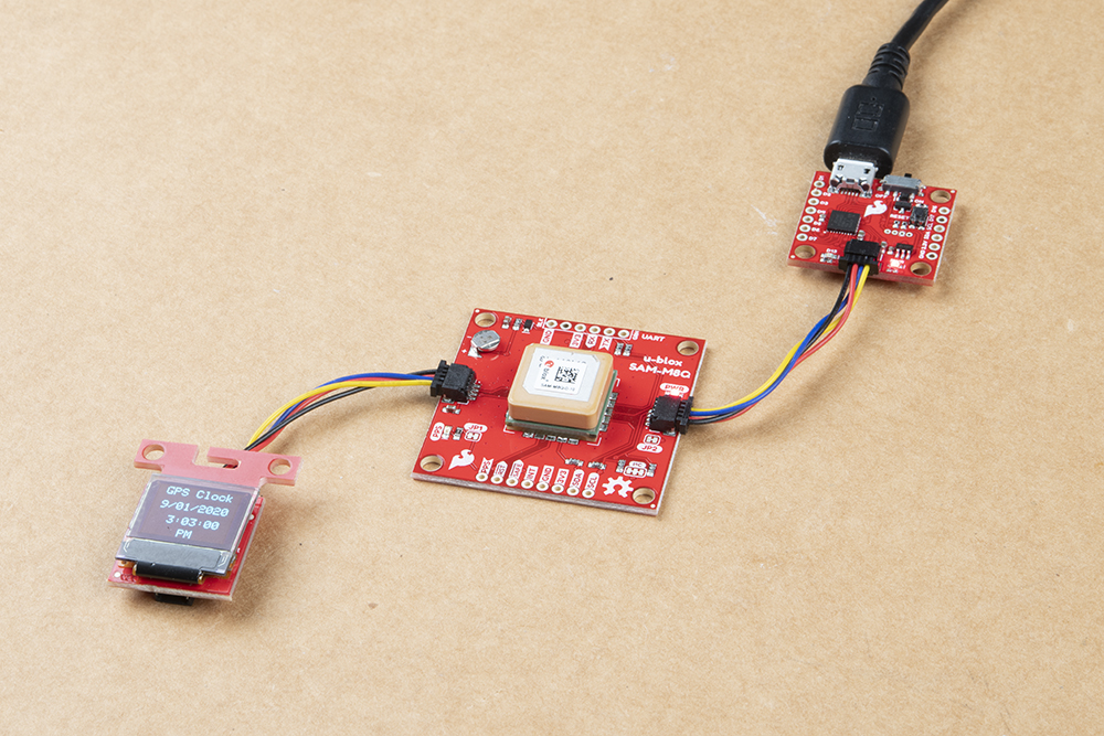
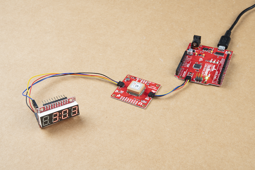
Based on the template, the following code is adjusted for the 7-segment serial display. This example is able to send the time to the I2C port by each Serial.print() statement. Before and after each stream of data, we'll also need to open/close the I2C bus for each transmission.
Since the 7-segment serial display was designed before the Qwiic system, we'll need to solder some headers to the board and use an adapter to connect the headers to the Qwiic connector easily. The LEDs for the 7-segement are bigger and can be seen farther away than the Qwiic micro OLED.
To follow along with this example, you will need the following materials. You may not need everything though depending on what you have. Add it to your cart, read through the guide, and adjust the cart as necessary.
If you decide to use the 7-Segment Serial Display, we recommend taking a look at the following tutorials about the 7-Segment Serial Display and how to solder as well.
Connecting the boards together is easy. Simply add a Qwiic cable between your Arduino and u-blox GPS module. In this case, we used the RedBoard Qwiic with ATmega328P and Qwiic GPS breakout with SAM-M8Q. We'll need to solder male headers to the I2C pins and +/- pins. To easily connect the pins to the Qwiic connector, we use a Qwiic cable with female sockets to match the colors to each respective pin arrangement. Soldering more than 4x male header pins is not necessary if you are just using the I2C bus.
Copy and paste the code in the Arduino IDE. Select the board (in this case the Arduino Uno) and COM port that it enumerated to. Hit the upload button.
language:c
/*
  Getting the time and date in your timezone using Ublox commands
  Originally Written By: davidallenmann
  Modified By: Ho Yun "Bobby" Chan
  SparkFun Electronics
  Date: April 16th, 2019
  License: MIT. See license file for more information but you can
  basically do whatever you want with this code.

  This is a modified example that shows how to query a Ublox module for the current time and date. We also
  turn off the NMEA output on the I2C port. This decreases the amount of I2C traffic
  dramatically.

  Leave NMEA parsing behind. Now you can simply ask the module for the datums you want!

  Additionally, this code has the option to adjust the UTC date and time. The time is adjusted by manually
  entering your time zone's offset. The Daylight Savings Time is automatically calculated with the help of
  Nathan Seidle's Daylight Savings Time example [ https://github.com/nseidle/Daylight_Savings_Time_Example ].
  However, if your country does not observe DST, you can override it with the `enableDST` variable.

  The output for this example is sent through a Serial UART port. Depending on personal preference, you can view
  the time in regular 12-hour format or miltary 24-hour format. Shout out to Jim for the I2C example 7-segment
  serial display!

  Feel like supporting open source hardware?
  Buy a board from SparkFun!
  ZED-F9P RTK2: https://www.sparkfun.com/products/15136
  NEO-M8P RTK: https://www.sparkfun.com/products/15005
  SAM-M8Q: https://www.sparkfun.com/products/15106

  Hardware Connections:
  Plug a Qwiic cable into the u-Blox Qwiic-enabled GPS and the Qwiic Micro. We will use a
  7-Segment Display. Since the board was designed before the Qwiic system, you will need
  to solder wires to a Qwiic adapter before connecting it with a Qwiic cable.
  If you don't have a platform with a Qwiic connection use the SparkFun Qwiic Female Jumper (https://www.sparkfun.com/products/14425)
  Open the serial monitor at 115200 baud to see the output.
*/

#include <Wire.h> //Needed for I2C to GPS
#include "SparkFun_Ublox_Arduino_Library.h" //http://librarymanager/All#SparkFun_Ublox_GPS
// Here we'll define the I2C address of our S7S. By default it
//  should be 0x71. This can be changed, though.
const byte s7sAddress = 0x71;

SFE_UBLOX_GPS myGPS;

long lastTime = 0; //Simple local timer. Limits amount if I2C traffic to Ublox module.
long latitude = 0;
long longitude = 0;
long altitude = 0;
byte SIV = 0;

boolean DST = false; //adjust for Daylight Savings Time, this is calculated automatically. fall back = FALSE, spring forward = TRUE
boolean enableDST = true; //option to disable DST if your country does not observe DST
int zoneOffsetHour = -7; //adjust according to your standard time zone
byte DoW = 0; //needed to adjust hour for DST, or if you want to know the Day of the Week
boolean military = false; //adjust for miltary or AM/PM
boolean AM = false; //AM or PM?

// Use these variables to set the initial time: 3:03:00
int hours = 3;
int minutes = 3;
int seconds = 0;

//for 7 segment display
int time_hourTemp = 0;
int time_minuteTemp = 0;
int time_secondTemp = 0;
char tempString[10];  // Will be used with sprintf to create strings


//Tid Bit: https://www.sparkfun.com/news/2571#yearOrigin
int years = 2003; //year that SparkFun was founded!
int months = 1;  //month that SparkFun was founded!
int days = 3;    //day that SparkFun was founded!

// How fast do you want the clock to update? Set this to 1 for fun.
// Set this to 1000 to get _about_ 1 second timing.
const int CLOCK_SPEED = 1000;
unsigned long lastDraw = 0;


void setup() {
  Serial.begin(115200);
  //while (!Serial)
  //  ; //Wait for user to open terminal
  Serial.println(F("SparkFun Ublox Example"));

  Wire.begin();
  Wire.setClock(400000);   // Set clock speed to be the fastest for better communication (fast mode)


  if (myGPS.begin() == false) //Connect to the Ublox module using Wire port
  {
    Serial.println(F("Ublox GPS not detected at default I2C address. Please check wiring. Freezing."));
    while (1)
      ;
  }

  myGPS.setI2COutput(COM_TYPE_UBX); //Set the I2C port to output UBX only (turn off NMEA noise)
  myGPS.saveConfiguration();        //Save the current settings to flash and BBR

  // Clear the display, and then turn on all segments and decimals
  clearDisplayI2C();  // Clears display, resets cursor

  delay(50);  //small delay so 7-segment display has time to pick up commands or characters

  // Custom function to send four bytes via I2C
  //  The I2C.write function only allows sending of a single
  //  byte at a time.
  s7sSendStringI2C("-HI-");
  setDecimalsI2C(0b010000);  // Turn on colon

  // Flash brightness values at the beginning
  setBrightnessI2C(0);  // Lowest brightness
  delay(1500);
  setBrightnessI2C(255);  // High brightness
  delay(1500);

  // Clear the display before jumping into loop
  clearDisplayI2C();

  delay(50); //small delay so 7-segment display has time to pick up commands or characters
  setDecimalsI2C(0b010000);  // Turn on colon

}

void loop() {

  update_Time();


  displayDigital_Date_Time();

} //end loop


// Simple function to increment seconds and then increment minutes
// and hours if necessary.
void update_Time() {

  //Query module only every second. Doing it more often will just cause I2C traffic.
  //The module only responds when a new position is available
  if (millis() - lastTime > 1000) {
    lastTime = millis(); //Update the timer

    latitude = myGPS.getLatitude();
    longitude = myGPS.getLongitude();
    altitude = myGPS.getAltitude();
    SIV = myGPS.getSIV();

    years = myGPS.getYear();
    months = myGPS.getMonth();
    days = myGPS.getDay();
    hours = myGPS.getHour();
    minutes = myGPS.getMinute();
    seconds = myGPS.getSecond();

    calcZone_DST(); //adjust zone and used to check if it is Daylight Savings Time

  }
  //Serial.print(F("Lat: "));
  //Serial.print(latitude);


  //Serial.print(F(" Long: "));
  //Serial.print(longitude);
  //Serial.print(F(" (degrees * 10^-7)"));


  //Serial.print(F(" Alt: "));
  //Serial.print(altitude);
  //Serial.print(F(" (mm)"));


  //Serial.print(F(" SIV: "));
  //Serial.print(SIV);

  //Serial.println();

}

//Nate's snazzy code!
//Given a year/month/day/current UTC/local offset give me local time
void calcZone_DST() {
  //Since 2007 DST starts on the second Sunday in March and ends the first Sunday of November
  //Let's just assume it's going to be this way for awhile (silly US government!)
  //Example from: http://stackoverflow.com/questions/5590429/calculating-daylight-savings-time-from-only-date

  DoW = day_of_week(); //Get the day of the week. 0 = Sunday, 6 = Saturday
  int previousSunday = days - DoW;

  //DST = false; //Assume we're not in DST
  if (enableDST == true) {
    if (months > 3 && months < 11) DST = true; //DST is happening!

    //In March, we are DST if our previous Sunday was on or after the 8th.
    if (months == 3)
    {
      if (previousSunday >= 8) DST = true;
    }
    //In November we must be before the first Sunday to be DST.
    //That means the previous Sunday must be before the 1st.
    if (months == 11)
    {
      if (previousSunday <= 0) DST = true;
    }
  }


  //adjust time for DST here if it applies to your region
  if (DST == true) {//adjust time Daylight Savings Time
    hours = hours + 1;
  }
  else { //leave time as is for Daylight Time
  }


  //adjust time based on Time Zone
  hours = hours + zoneOffsetHour;

  //adjust for offset zones when hour is negative value
  if (hours < 0) {
    days = days - 1;

    hours = hours + 24;
  }
  else if ( hours > 23)    {
    days = days + 1;

    hours = hours - 24;
  }


  //adjust for AM/PM mode
  if (military == false) {
    if (hours >= 0 && hours <= 11) {// we are in AM
      if (hours == 0) {
        hours = 12;
      }
      AM = true;
    }
    else { // hours >= 12 && hours <= 23, therefore we are in PM!!!
      if (hours > 12  && hours <= 23) {
        hours = hours - 12;
      }
      AM = false;
    }

  }


  /*
    Serial.print("Hour: ");
    Serial.println(hour);
    Serial.print("Day of week: ");
    if(DoW == 0) Serial.println("Sunday");
    if(DoW == 1) Serial.println("Monday");
    if(DoW == 2) Serial.println("Tuesday");
    if(DoW == 3) Serial.println("Wednesday");
    if(DoW == 4) Serial.println("Thursday");
    if(DoW == 5) Serial.println("Friday!");
    if(DoW == 6) Serial.println("Saturday");
  */

}


//Given the current year/month/day
//Returns 0 (Sunday) through 6 (Saturday) for the day of the week
//From: http://en.wikipedia.org/wiki/Calculating_the_day_of_the_week
//This function assumes the month from the caller is 1-12
char day_of_week() {
  //Devised by Tomohiko Sakamoto in 1993, it is accurate for any Gregorian date:
  static int t[] = { 0, 3, 2, 5, 0, 3, 5, 1, 4, 6, 2, 4  };
  years -= months < 3;
  return (years + years / 4 - years / 100 + years / 400 + t[months - 1] + days) % 7;
}


void displayDigital_Date_Time() {
  if (lastDraw + CLOCK_SPEED < millis())
  {
    lastDraw = millis();

    Serial.print(F("Date: "));

    if (months <= 9) {
      Serial.print(F(" "));
    }
    Serial.print(String(months) + '-');


    if (days <= 9) {
      Serial.print(F("0"));
    }
    Serial.println(String(days) + '-' + String(years));


    Serial.print(F("Time: "));


    if (hours <= 9) {
      Serial.print(' ');
      Wire.beginTransmission(s7sAddress);
      Wire.write(0x7B); // special command to control Digit 1
      Wire.write(0b00000000);
      Wire.endTransmission();
      delay(50); //small delay so 7-segment display has time to pick up commands or characters
      if (time_hourTemp != hours) {
        Wire.beginTransmission(s7sAddress);
        Wire.write(0x79); // special command to cursor control
        Wire.write(0x01);
        Wire.endTransmission();
        delay(50); //small delay so 7-segment display has time to pick up commands or characters
        // Magical sprintf creates a string for us to send to the s7s.
        //  The %1d option creates a 1-digit integer.
        sprintf(tempString, "%1d", hours);
        // This will output the tempString to the S7S
        s7sSendCharI2C(tempString);
        time_hourTemp = hours;
      }
    }
    if (time_hourTemp != hours) {
      Wire.beginTransmission(s7sAddress);
      Wire.write(0x79);
      Wire.write(0x00);
      Wire.endTransmission();
      delay(50); //small delay so 7-segment display has time to pick up commands or characters

      // Magical sprintf creates a string for us to send to the s7s.
      //  The %2d option creates a 1-digit integer.
      sprintf(tempString, "%2d", hours);
      // This will output the tempString to the S7S
      s7sSend2xCharI2C(tempString);
      time_hourTemp = hours;

    }

    Serial.print(String(hours) + ':' );


    if (minutes <= 9) {
      Serial.print(F("0"));
      Wire.beginTransmission(s7sAddress);
      Wire.write(0x7D); //special command to control Digit 3
      Wire.write(0b00111111);
      Wire.endTransmission();
      delay(50); //small delay so 7-segment display has time to pick up commands or characters
      if (time_minuteTemp != minutes) {
        Wire.beginTransmission(s7sAddress);
        Wire.write(0x79); //special command to cursor control
        Wire.write(0x03);
        Wire.endTransmission();
        delay(50); //small delay so 7-segment display has time to pick up commands or characters
        // Magical sprintf creates a string for us to send to the s7s.
        //  The %1d option creates a 1-digit integer.
        sprintf(tempString, "%1d", minutes);
        // This will output the tempString to the S7S
        s7sSendCharI2C(tempString);
        time_minuteTemp = minutes;
      }
    }
    if (time_minuteTemp != minutes) {
      Wire.beginTransmission(s7sAddress);
      Wire.write(0x79); //special command to cursor control
      Wire.write(0x02);
      Wire.endTransmission();
      delay(50); //small delay so 7-segment display has time to pick up commands or characters
      // Magical sprintf creates a string for us to send to the s7s.
      //  The %2d option creates a 1-digit integer.
      sprintf(tempString, "%2d", minutes);
      // This will output the tempString to the S7S
      s7sSend2xCharI2C(tempString);
      time_minuteTemp = minutes;
    }

    Serial.print(String(minutes) + ':');


    if (seconds <= 9) {
      Serial.print(F("0"));

    }
    Serial.print(String(seconds));


    if (military == false) {
      if (AM == true) {

        Serial.println(F(" AM"));
      }
      else {
        if (AM == false) {
          Serial.println(F(" PM"));
        }
      }
    }
    else {
      Serial.println(); //space between military time for Serial Monitor
    }

    if (myGPS.getDateValid() == false) {
      Serial.println(F("Date is invalid, not enough satellites in view!"));
    }
    if (myGPS.getTimeValid() == false) {
      Wire.beginTransmission(s7sAddress);
      Wire.write(0x7B); // Digit 1 control
      Wire.write(0b01000000); // display `-`
      Wire.write(0x7C); // Digit 2 control
      Wire.write(0b01000000); // display `-`
      Wire.write(0x7D);  // Digit 3 control
      Wire.write(0b01000000); // display `-`
      Wire.write(0x7E); // Digit 4 control
      Wire.write(0b01000000); // display `-`
      Wire.endTransmission();
      delay(50); //small delay so 7-segment display has time to pick up commands or characters

      Serial.println(F("Time is invalid, not enough satellites in view!"));
    }

    Serial.println();
  }

}


// This custom function works somewhat like a serial.print.
//  You can send it an array of chars (string) and it'll print
//  the first 4 characters in the array.
void s7sSendStringI2C(String toSend) {
  Wire.beginTransmission(s7sAddress);
  for (int i = 0; i < 4; i++)
  {
    Wire.write(toSend[i]);
  }
  Wire.endTransmission();
}

// This custom function works somewhat like a serial.print.
//  You can send it an array of chars (string) and it'll print
//  the first character in the array.
void s7sSendCharI2C(String toSend) {
  Wire.beginTransmission(s7sAddress);
  for (int i = 0; i < 1; i++)
  {
    Wire.write(toSend[i]);
  }
  Wire.endTransmission();
}

// This custom function works somewhat like a serial.print.
//  You can send it an array of chars (string) and it'll print
//  the first character in the array.
void s7sSend2xCharI2C(String toSend) {
  Wire.beginTransmission(s7sAddress);
  for (int i = 0; i < 2; i++)
  {
    Wire.write(toSend[i]);
  }
  Wire.endTransmission();
}


// Send the clear display command (0x76)
//  This will clear the display and reset the cursor
void clearDisplayI2C() {
  Wire.beginTransmission(s7sAddress);
  Wire.write(0x76);  // Clear display command
  Wire.endTransmission();
}


// Set the displays brightness. Should receive byte with the value
//  to set the brightness to
//  dimmest------------->brightest
//     0--------127--------255
void setBrightnessI2C(byte value) {
  Wire.beginTransmission(s7sAddress);
  Wire.write(0x7A);  // Set brightness command byte
  Wire.write(value);  // brightness data byte
  Wire.endTransmission();
}


// Turn on any, none, or all of the decimals.
//  The six lowest bits in the decimals parameter sets a decimal
//  (or colon, or apostrophe) on or off. A 1 indicates on, 0 off.
//  [MSB] (X)(X)(Apos)(Colon)(Digit 4)(Digit 3)(Digit2)(Digit1)
void setDecimalsI2C(byte decimals) {
  Wire.beginTransmission(s7sAddress);
  Wire.write(0x77);
  Wire.write(decimals);
  Wire.endTransmission();
}
The code in this example is pretty much the same as the template. To switch from AM/PM to military format, you will need to set military to true. Depending on your region, you will need to adjust the enableDST and zoneOffsetHour accordingly. You will also need to adjust the condition statements at the beginning of the calcZone_DST() function for region since the DST starts/ends on different days of the month.
The difference is that we sent data via I2C by each Serial.print() statement. There were a few 50ms delays included between each transmission to ensure that the 7-segment serial display had enough time to receive the commands and data. With the limited amount of space on the display, only the hour and time was shown. If there was additional 7-segment displays with different addresses on the I2C bus, we could display the seconds or date.
If you adjusted the zoneOffsetHour, enableDST, and code at the begnning of the calcZone_DST() function to your region and still have trouble getting the correct date/time, there may not be enough satellites in view. You may need to wait a bit longer for the GPS module to get the date/time. Depending on the display, you'll notice the !D, !T, X, or "--:--" when the date and time is not valid.
If you still have problems, you may want to consider moving the GPS clock to a different location to avoid problems with RF interference, urban canyons, or harsh environments (e.g. a concrete building). Try adjusting the code to read the amount of satellites in view using example 0 by removing the single line comments // inside the update_Time() function.
language:c
  //Serial.print(F(" SIV: "));
  //Serial.print(SIV);
All it takes is at least one GPS satellite to zoom by for the GPS module to latch onto the date and time. Luckily, you do not need to have a GPS lock for this to happen. As long as it is powered up, the GPS will keep ticking away. If there is a power cycle, you'll need to be patient for it to pick up another stream of data. For more information, check out the tutorial linked below. Note that the Alphanumeric GPS Wall Clock tutorial uses a different GPS library and a Serial UART.
If your code compiles with the following warning, this may be caused by the resources being used and the size of the Arduino's RAM.
language:bash
"Low memory available, stability problems may occur"
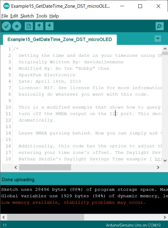
Depending on how many resources are being used, this may affect the performance of the code when displaying the date or time. There are a few methods to avoid the warning or reduce the probability of an issue occuring when the code is running. This is briefly explained in the Qwiic micro OLED example
For more information, check out the resources below:
Need some inspiration for your next project? Check out some of these related tutorials tagged with time! Instead of a GPS module, try using a Real Time Clock (RTC) or grabbing the current time from the Internet. Or modify the code to display the time using addressable LEDs or an RGB matrix panel. Want to save your LCD or micro OLED from burn-in? Try adding code to turn off the display and wake it up using a distance sensor. Better yet, make an analog clock made out of LuMini LED Rings!
Looking for a challenge? Try making a 12" 7-segment GPS Wall Clock and some addressable LEDs:

For more information on the updated GPS Clock in the SparkFun Emporium, check out the Big_GPS_Clock GitHub repo.
learn.sparkfun.com | CC BY-SA 3.0 | SparkFun Electronics | Niwot, Colorado