Qwiic EEPROM Hookup Guide
Hardware Overview
Board Dimensions
The Qwiic EEPROM Breakout is laid out on the standardized 1" x 1" (2.54 x 2.54 cm) Qwiic breakout board and includes the standard four 0.13" mounting holes, which are compatible with 4-40 screws.

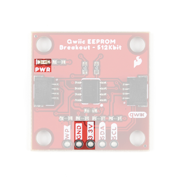
Power
There is a power status LED to help make sure that your Qwiic EEPROM is getting power. You can power the board either through the polarized Qwiic connector system or the breakout pins (3.3V and GND) provided. The Qwiic system is meant to run on 3.3V, be sure that you are NOT using another voltage when using the Qwiic system.
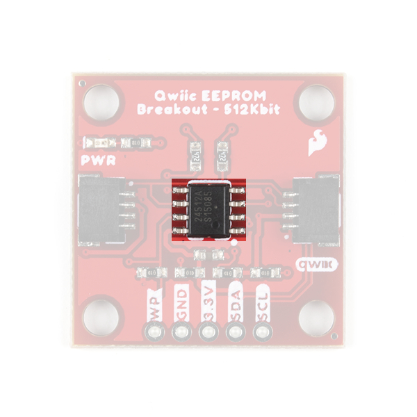
CAT24C512 EEPROM
The CAT24C512 IC is a 512-Kb (kilobit) EEPROM flash memory is organized as 65,536 words of 8 bits each with a 128-byte page write buffer. An on board ECC (Error Correction Code) makes this EEPROM suitable for high reliability applications. The IC also offers write protection, which inhibits write operations by pulling the WP pin High (protects the entire memory). The external address pins make it possible to connect up to eight CAT24C512 EEPROM chips on the same I2C bus.
For more details on how the serial EEPROM works, check out our guide below:
Reading and Writing Serial EEPROMs
Sensor Characteristics
Below, is a table of the characteristics of the EEPROM chip. For more details, please refer to the datasheet.
| Characteristic | Description |
|---|---|
| Power |
Supply Voltage: 1.8 to 5.5V Supply Current:
|
| Reliability |
Endurance: 1,000,000 Program/Erase Cycles Data Retention: 100 Years |
| Page Write Buffer | 128 bytes |
| Write Protection | Entire Memory |
| I2C Address (7-bit) |
1010[E2][E1][E0] 0x50 (Default), 0x51, 0x52, 0x53, 0x54, 0x55, 0x56, 0x57 |
Qwiic and I2C
I2C Address
The Qwiic EEPROM’s I2C address, 0x50 (7-bit), is factory set. An alternate I2C address can be configured to 1010[E2][E1][E0] by modifying the address jumpers E0, E1, E2 (see Jumpers section below).
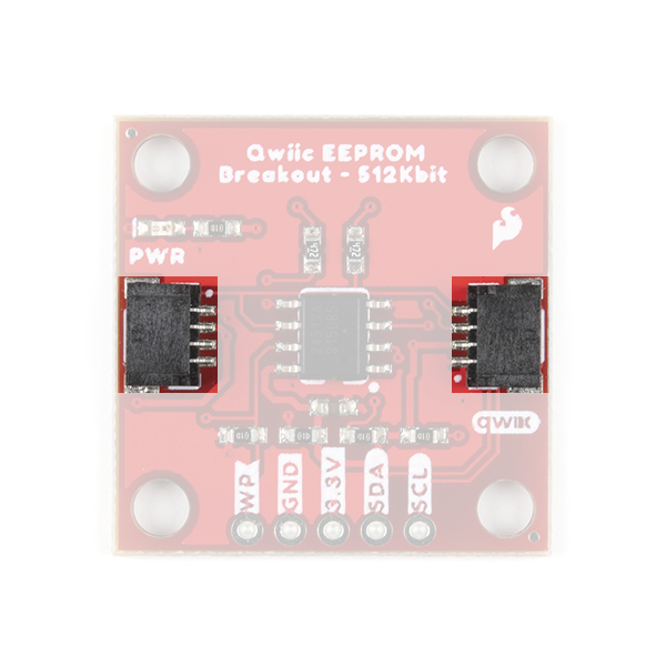
Qwiic Connectors
The simplest way to use the Qwiic EEPROM is through the Qwiic connect system. The connectors are polarized for the I2C connection and power. (*They are tied to the corresponding power and I2C breakout pins.)
Breakout Pins
The board also provides five labeled breakout pins.
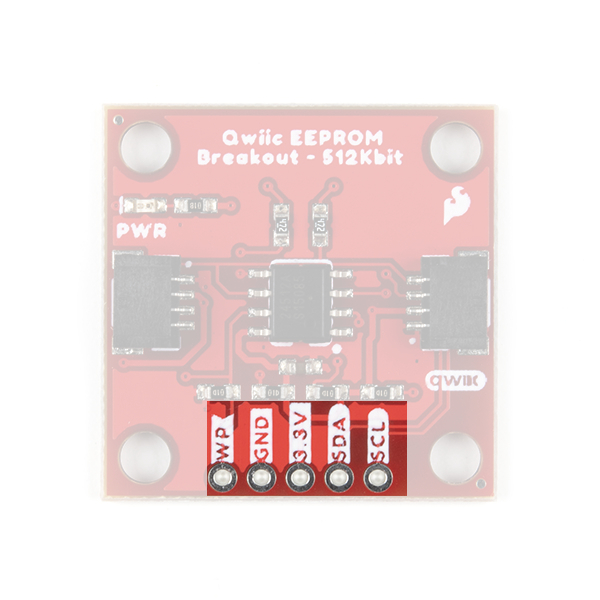
I2C
You can connect these lines to the I2C bus of your microcontroller and power pins (3.3V and GND), for a more permanent connection.
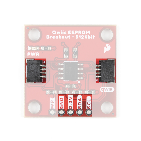
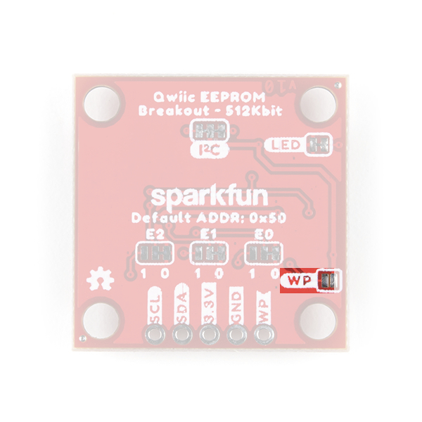
Write Protection Pin
Pulling the WP pin high, will disable all write operations to the entire memory space.

Jumpers
There are five jumpers on the board. Not sure how to cut or modify a jumper? Read here!
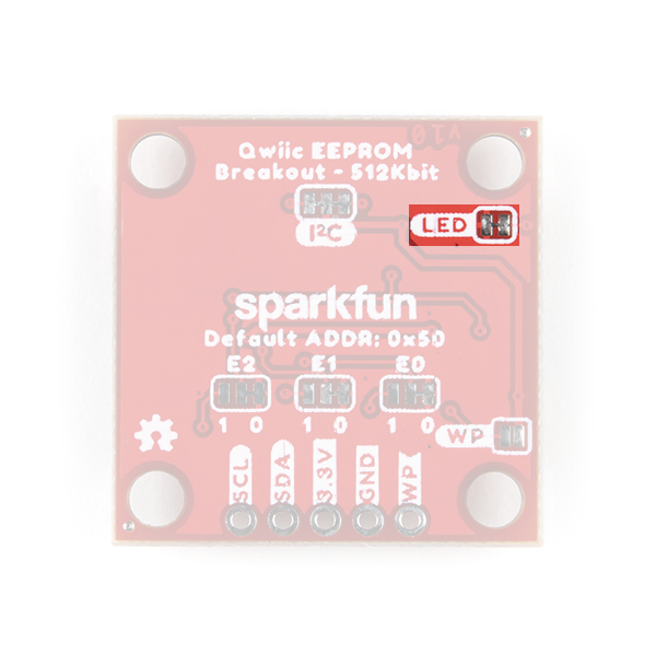
Power LED Jumper
Cutting the LED jumper will remove the 1kΩ resistors and PWR LED from the 3.3V power. This is useful for low power applications.
Write Protection
Bridging the WP jumper will pull the pin high (to the 3.3V power) and disable any write operations.
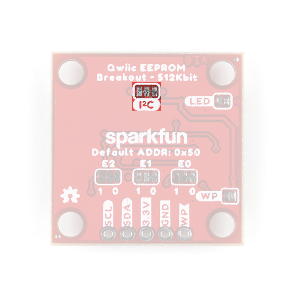
I2C Pull-Up
Cutting the I2C jumper will remove the 2.2kΩ pull-up resistors from the I2C bus. If you have many devices on your I2C bus you may want to remove these jumpers.
Address Jumpers
Modifying the address jumpers (E0, E1, E2) allows users to configure the I2C address. This can be used to configure the default I2C address of the device to 1010[E2][E1][E0] (7-bit).
