$25.50
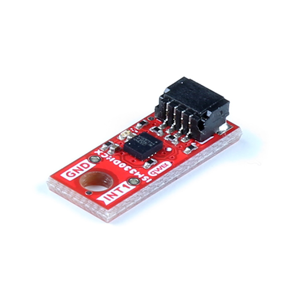
Do you need 6 degrees of freedom? We do! Behold the SparkFun Qwiic 6DoF - ISM330DHCX and the SparkFun Micro 6DoF IMU Breakout - ISM330DHCX (Qwiic) - both of which are Qwiic enabled breakouts featuring STMicroelectronics' ISM330DHCX; a high-performance 3D digital accelerometer and 3D digital gyroscope tailored for Industry 4.0 applications such as platform, optical image, and lens stabilization, robotics and industrial automation, navigations systems, and vibration monitoring and compensation.
Both of these accelerometers have a full-scale acceleration range of ±2/±4/±8/±16 g and a wide angular rate range of ±125/±250/±500/±1000/±2000/±4000 dps that enable its usage in a broad range of applications. An unmatched set of embedded features (Machine Learning Core, programmable FSM, FIFO, sensor hub, event decoding and interrupts) are enablers for implementing smart and complex sensor nodes which deliver high performance at very low power.
The full sized SparkFun Qwiic 6DoF - ISM330DHCX boasts the standard 1x1" form factor, while the Micro 6DoF IMU breakout clocks in at a teeny tiny 0.75 x 0.3 inches!
To follow along with this tutorial, you will need the following materials. You may not need everything though depending on what you have. Add it to your cart, read through the guide, and adjust the cart as necessary.
If you aren’t familiar with the following concepts, we recommend checking out these tutorials before continuing.
The ISM330DHCX is a small, system-in-package from STMicroelectronics featuring a high-performance 3D digital accelerometer and 3D digital gyroscope capable of wide bandwidth, ultra-low noise and a selectable full-scale range of ±2/±4/±8/±16 g. The 3D gyroscope has an angular rate range of ±125/±250/±500/±1000/±2000/±4000 dps and offers superior stability over temperature and time along with ultra-low noise.
 |
 |
| ISM330DHCX on the Qwiic 6DoF 1x1" Breakout | ISM330DHCX on the Qwiic Micro 6DoF Breakout |
The ISM330DHCX can run in four different modes:
This is the default "peripheral only" mode. This mode allows you to use either I2C or SPI. By default, I2C is enabled with an address of 0x6B. By manipulating the associated jumper, you can change the I2C address to 0x6A (cut the power side and close the ground side) or switch to SPI mode (both jumpers open).
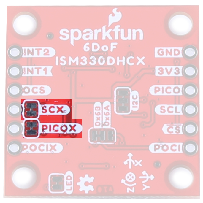
This mode enables a secondary I2C port that the 6DoF controls; up to 4 external sensors can be connected to the I2C controller interface of the device. External sensors communicate via the SCX and SDX (PICOX) lines - the SCX jumper will need to be opened.
In addition to the primary I²C peripheral interface or SPI (3- / 4-wire) serial interface, an auxiliary SPI (3- / 4-wire) serial interface is available for external device connections (i.e. camera module). Mode 3 is available for gyroscope only, Mode 4 is available for both gyroscope and accelerometer.
Our Qwiic Ecosystem makes sensors pretty much plug and play. There are two Qwiic connectors on the side of the Qwiic 6DoF - ISM330DHCX board and one Qwiic connector on the side of the Qwiic Micro 6DoF to provide power and I2C connectivity simultaneously.
 |
 |
| Qwiic connectors on the Qwiic 6DoF 1x1" Breakout | Qwiic connector on the Qwiic Micro 6DoF Breakout |
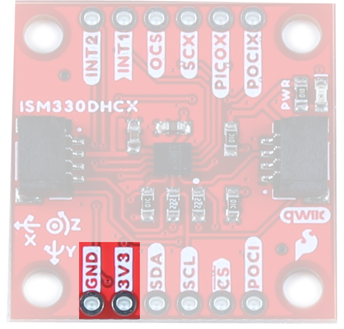
Ideally, power will be supplied via the Qwiic connectors, but we've also broken out plated through hole pins to supply 3.3V and Ground, should you prefer. Make sure to pay attention to logic levels - supply voltage to this board should range from 1.71 V to 3.6 V.
For flexibility, we've broken out the I2C functionality as seen below. Primary I2C pins are broken out to SDA and SCL:

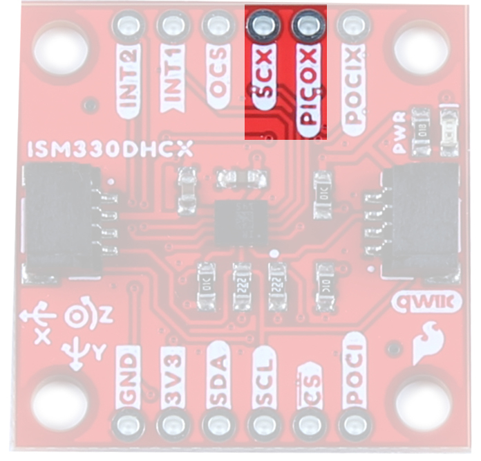
Secondary I2C pins are broken out to SDX/PICOX and SCX. These pins are used solely for Mode 2- Sensor Hub Mode - where the 6DoF reads other sensors. You must cut the PICOX and SCX jumpers on the back of the board in order to use this mode.
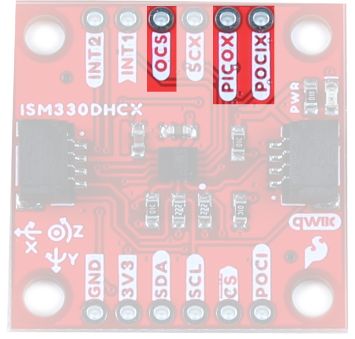
Like the I2C functionality, we've also broken out the SPI functionality to PTH pins on either side of the board.
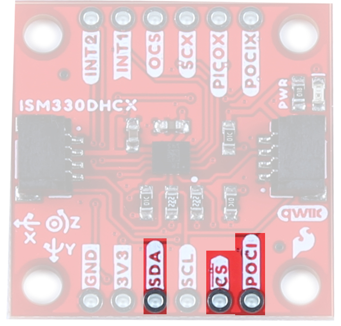
OCS is the enable pin for Modes 3 and 4. POCIX is used for one way communication in Mode 3, PICOX and POCIX are used for 2-way communication in Mode 4.
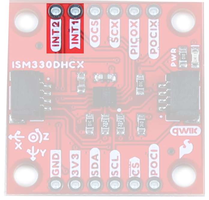
Interrupt generation can be sourced by the gyroscope or accelerometer; for interrupt-generation purposes, the accelerometer/gyroscope sensor has to be set in an active operating mode (not in Power-Down). In addition, the second interrupt pin can also generate signals for the accelerometer and gyroscope, but also for the temperature sensor.
The second interrupt (INT2) can also be configured as an INPUT to the 6DoF. This is primarily used in sensor-hub mode (Mode 2) as a way of signaling that data is ready on one of the attached sensors.
The interrupt generator can be configured to detect:
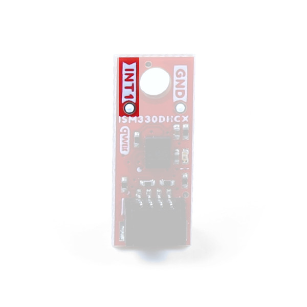
We've broken out a single PTH pin for Interrupt functionality on the Qwiic 6DoF - ISM330DHCX Micro Breakout.
Like our other Qwiic boards, the Qwiic 6DoF - ISM330DHCX comes equipped with pull-up resistors on the clock and data pins. If you are daisy-chaining multiple Qwiic devices, you will want to cut this jumper; if multiple sensors are connected to the bus with the pull-up resistors enabled, the parallel equivalent resistance will create too strong of a pull-up for the bus to operate correctly. As a general rule of thumb, disable all but one pair of pull-up resistors if multiple devices are connected to the bus. To disable the pull up resistors, use an X-acto knife to cut the joint between the two jumper pads highlighted below.
 |
 |
| I2C Jumper on the Qwiic 6DoF 1x1" Breakout | I2C Jumper on the Qwiic Micro 6DoF Breakout |
If power consumption is an issue, cutting this jumper will disable the Power LED on the front of the board.
 |
 |
| LED Jumper on the Qwiic 6DoF 1x1" Breakout | LED Jumper on the Qwiic Micro 6DoF Breakout |
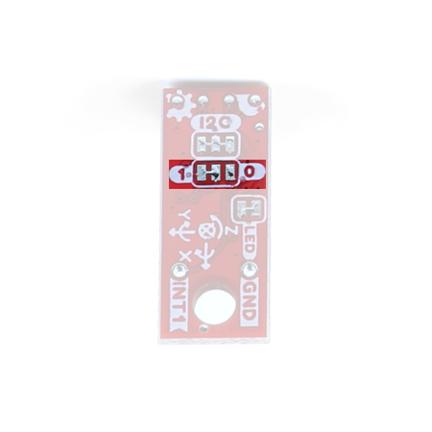
By default, I2C is enabled with an address of 0x6B. By manipulating this jumper, you can change the I2C address to 0x6A (cut the power side and close the ground side) or switch to SPI mode (both jumpers open).
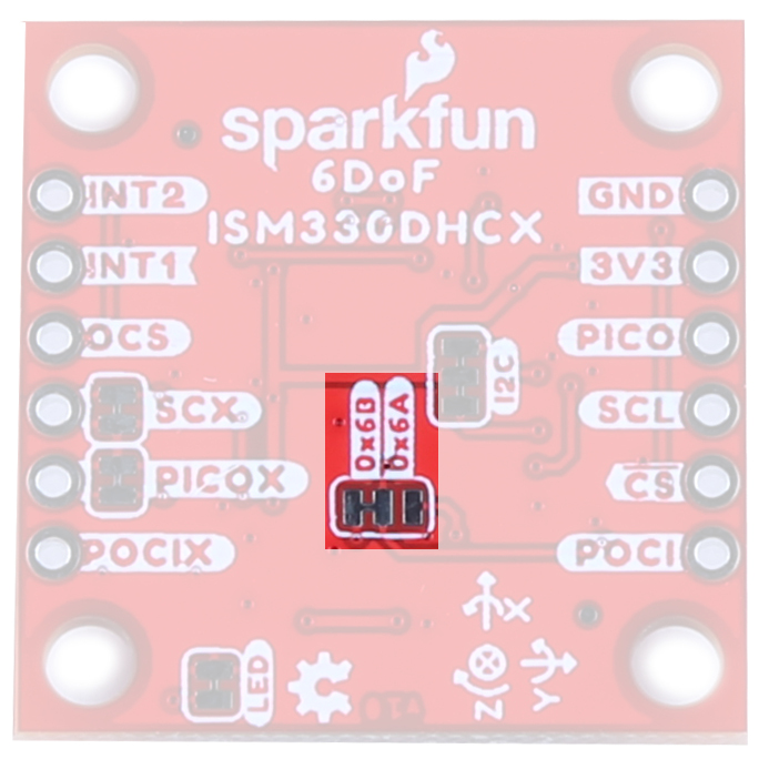
SPI is not available on the Qwiic Micro Breakout, but you can select the I2C address on the back of the board by closing either side of this trace.
| Address | ||
|---|---|---|
| 1 | VDD | 0x6B |
| 0 | GND | 0x6A |
| OPEN | SPI Not Supported | |
The SCX and PICOX pins are specific to Mode 2 and are used for peripheral communication. By default they are closed - to use Mode 2 you will need to cut both traces to open the jumper.
The Qwiic 6DoF - ISM330DHCX Breakout measures 1" x 1".

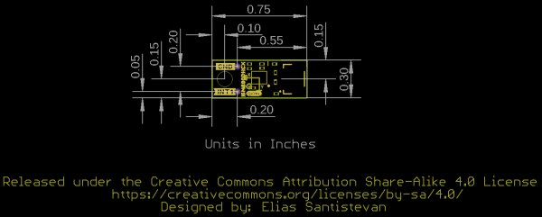
The Micro 6DoF IMU Breakout - ISM330DHCX (Qwiic) measures 0.75" x 0.3".

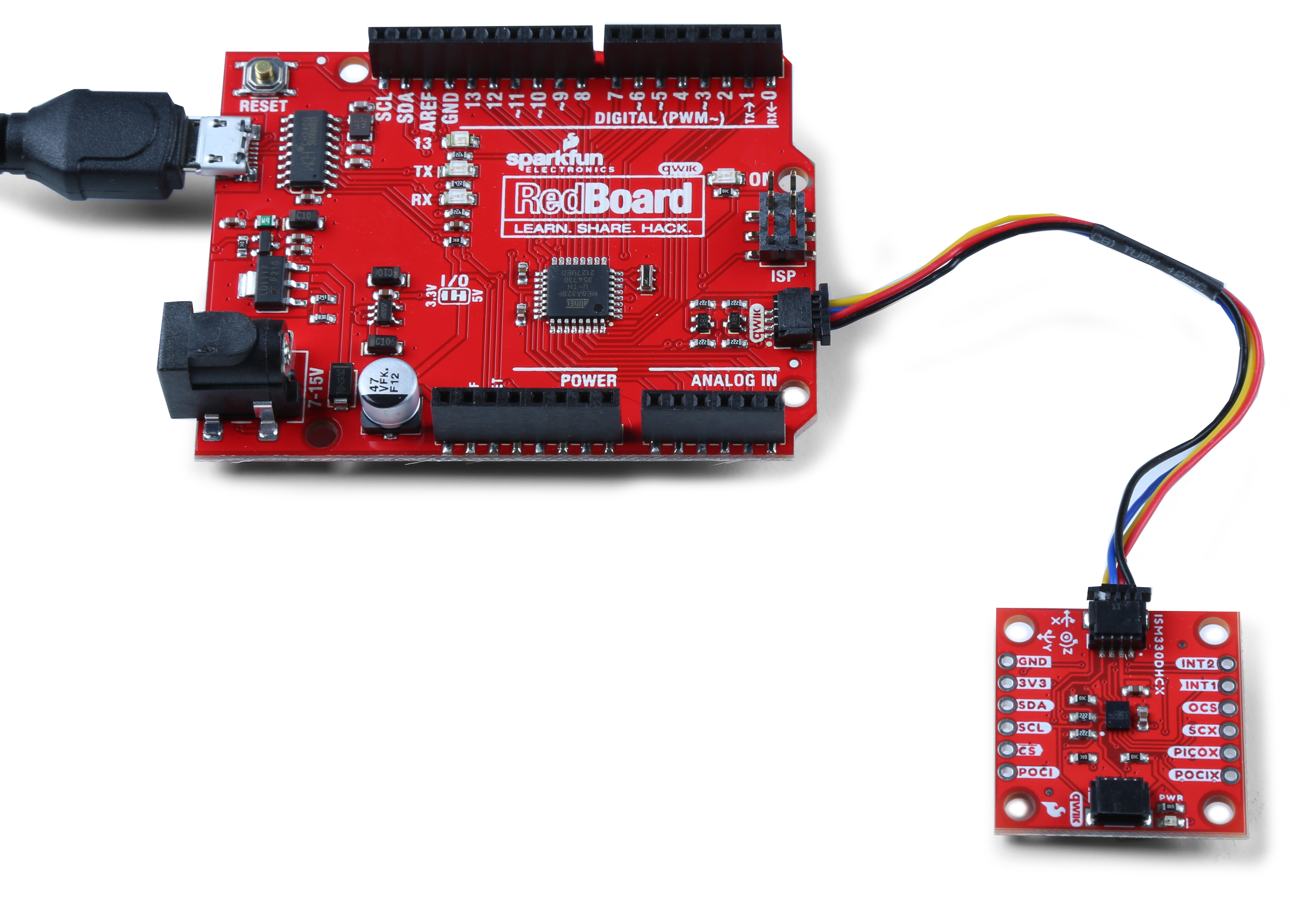
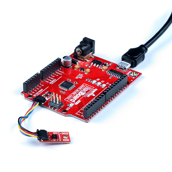
With the Qwiic connector system, assembling the hardware is simple. All you need to do is connect either your SparkFun Qwiic 6DoF - ISM330DHCX or your SparkFun Micro 6DoF IMU Breakout - ISM330DHCX (Qwiic) to the RedBoard Qwiic with a Qwiic cable. Otherwise, you can use the I2C pins of your microcontroller; just be aware of logic levels.
We've written a simple Arduino library to quickly get started reading data from the ISM330DHCX. Install the library through the Arduino Library Manager tool by searching for "SparkFun Qwiic 6DoF - ISM330DHCX". Users who prefer to manually install it can get the library from the GitHub Repository or download the ZIP by clicking the button below:
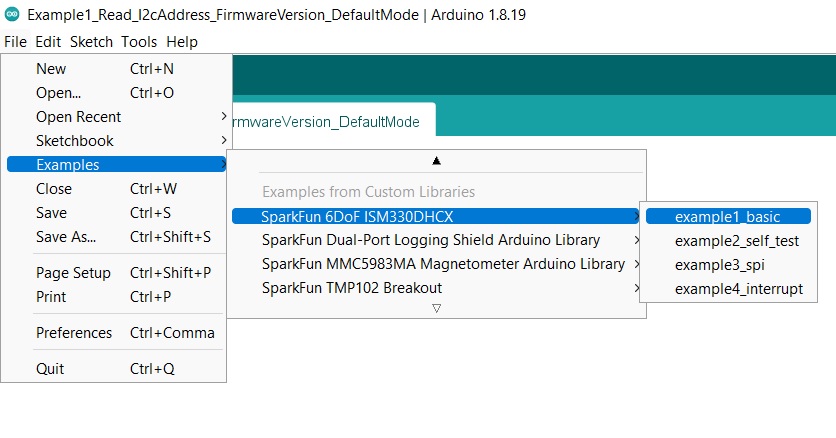
The first example initializes the 6DoF to communicate over I2C with default settings. Open the example by navigating to File Examples > SparkFun 6DOF ISM330DHCX > example1_basic. Select your Board and Port and click upload.
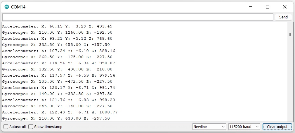
Open the serial monitor after the upload completes with the baud set to 115200 to watch data print out.
Now that you've successfully got your Qwiic 6DoF or 6DoF Micro up and running, it's time to incorporate it into your own project!
For more information, check out the resources below:
Need some inspiration for your next project? Check out some of these related tutorials:
learn.sparkfun.com | CC BY-SA 3.0 | SparkFun Electronics | Niwot, Colorado