Power Delivery Board - USB-C (Qwiic) Hookup Guide
 Alex the Giant, Ell C
USB-C Power Negotiation
Power Data Objects (PDOs)
The STUSB4500 has a set of user defined parameters that can be customized using the NVM re-programming through the I2C interface. This allows for changing the preset configuration of the power delivery interface and define new configurations based on specific application requirements.
On power-up, or after a hard reset, the NVM parameters are copied into the I2C registers and used by the controller during the system operation. After a soft reset, the controller will use the values saved in I2C registers to re-negotiate with the source. The controller can store up to three PDOs, with PDO3 having the highest priority and PDO1 having the lowest. After the NVM parameters have been copied to the I2C registers, the STUSB4500 will ask the source for it's capabilities to find a PDO match.
Each PDO has four parameters as shown in the table below:
| Parameter | Value Range | Notes |
|---|---|---|
| Voltage | 5 - 20 (V) | PDO1 is fixed at 5V and cannot be changed. |
| Over Voltage Tolerance | 5 - 20 (%) | Sets the upper voltage tolerance. For example, say this parameter is set to 5% and the voltage is set to 9V. If the supply voltage goes above 9.45V, the output (VSNK) will turn off. |
| Under Voltage Tolerance | 5 - 20 (%) | Sets the lower voltage tolerance for PDO2 and PDO3 only. For example, say this parameter is set to 5%, and the voltage is set to 9V. If the supply voltage drops below 8.55V, the output (VSNK) will turn off. PDO1 has a fixed under voltage limit of 3.3V and cannot be changed. |
| Current | 0 - 5 (A) | 16 possible values, see setCurrent function in Arduino Library secton for exact values. |
Each source might have a slightly different voltages listed on the case. One charger might advertise 12V, while another might advertise 12.3V perhaps to compensate for voltage drop across the cable, while another might say 11.5V to indicate the voltage at the end of the cable under the full load. Most sources though will advertise some combination of 5V, 9V, 12V, 15V, or 20V when negotiating with the consumer.
The current should be the maximum amount of current that the Power Delivery board expects to draw from the source. The STUSB4500 is not able to measure the actual current draw and will allow as much current as the source is able to deliver. If the current parameter is less than or equal to the max current the source advertised, the controller will send a request to source for that power profile. If the voltage or current parameters do not match with one of the capabilities of the source, the controller will try the next PDO to find a match with the source.
If the source accepts the contract, the source will switch from the defaulted VBUS voltage of 5V, to the voltage that was requested, and the VBUS_EN_SINK pin will be pulled low, and enable current to flow through the MOSFET which controls power to the VSNK power output pin.
Power Delivery Contract between Source and Sink
With the "U" in USB standing for Universal, when two devices are connected there are a bunch of messages sent between them to figure out what each device is connected to, and what each device supports. For the sake of simplicity, we're only going to look at the power delivery contract from a high level to understand what's going on.
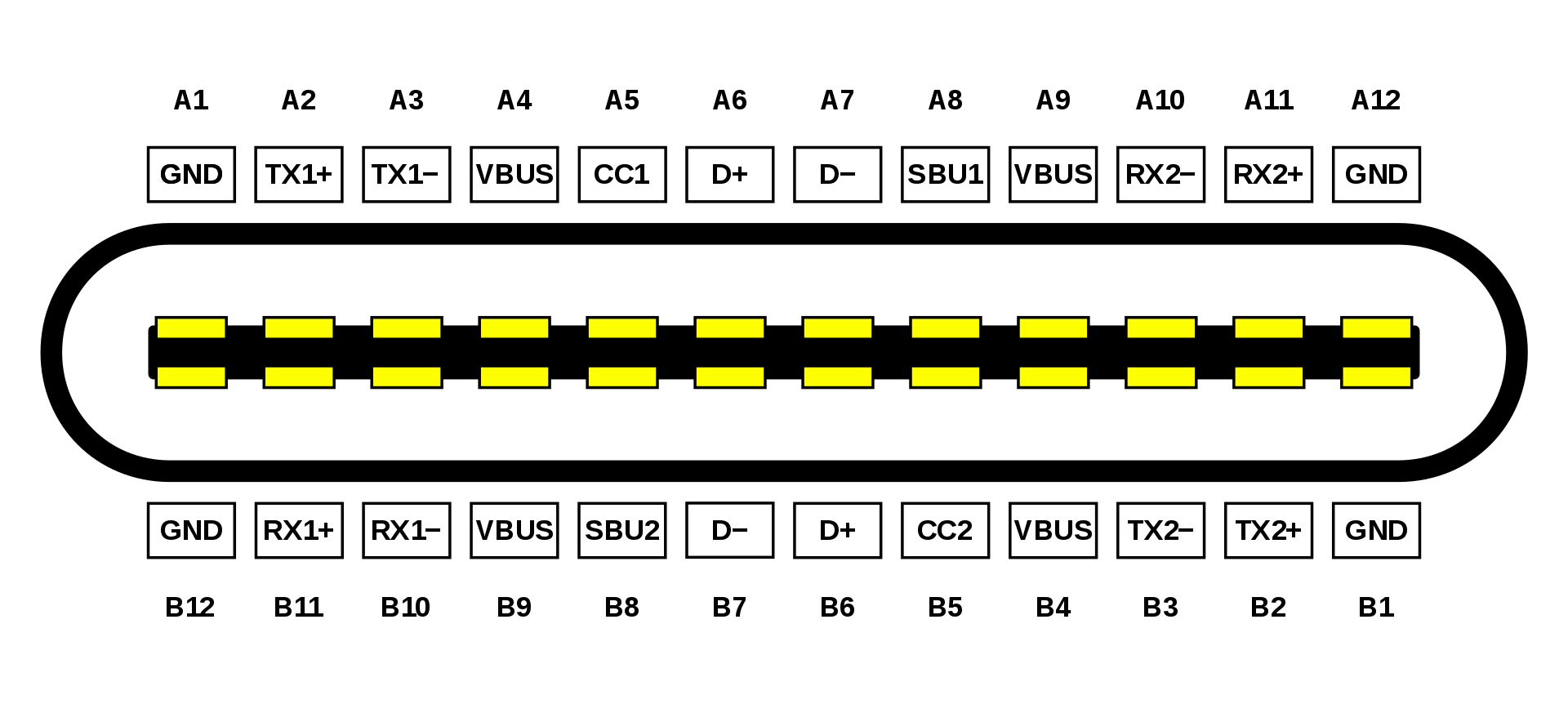
Of the 24 pins of the USB Type-C connector (shown above), the STUSB4500 only connects directly to 10 of these: 4 pins are used for VBUS, another 4 pins to ground, and the 2 channel configuration, or CC, pins. Depending on the cable orientation, one of these CC pins is used to send and receive messages between the sink and source. When a sink device connects to a source, the voltage on the VBUS starts off at 5V, just like the old USB standard.
Shortly after the source and sink are connected, the source will advertise it's capabilities as a power source, such as 5V@3A, 9V@2A, and any other power delivery options it's capable of. After that message is received, the controller will look at the PDO options available to find a match. Upon a match, the controller will ask for one of the voltage and current options. After the source accepts, the voltage is then switched to the voltage requested.
To find a match, the STUSB4500 controller first looks at the SNK_PDO_NUMB parameter, which is an integer value between 1 and 3, which corresponds to the highest priority PDO number. If the SNK_PDO_NUMB has a value of 3, it will first check to see if the source is able to provide PDO3, if not it will check PDO2, followed by PDO1. If SNK_PDO_NUMB has a value of 2, it will start by checking PDO2, followed by PDO1, and ignore PDO3. Finally if SNK_PDO_NUMB has a value of 1, it will only check PDO1. The two values the controller looks at to find a match are the voltage and current. As previously mentioned, most of the power delivery adapters will have a combination of 5V, 9V, 12V, 15V, and 20V. The packaging might say 5.2V or 20.3V, but in the capabilities message they'll actually specify 5V or 20V.
The other portion of the contract is the current being requested. If the voltage is accepted, but is only capable of delivering 1.5A of current at that voltage, but 2.0A of current was requested, that contract will be rejected by the source even though the source was capable of supplying that voltage. Alternatively, requesting 0.5A of current with a source capable of delivering 1.5A will be accepted. The amount of current requested should be about is expected for the project, but the source will allow the sink to draw more current than requested, up to the limit of that power delivery option.