Power Delivery Board - USB-C (Qwiic) Hookup Guide
 Alex the Giant, Ell C
Arduino Library Examples
In these examples, we'll connect our Power Delivery board to a RedBoard Qwiic using a Qwiic cable. The Type-C power adapter used in these examples is an Apple 87W USB-C Power Adapter which has an output of 20.3V/4.3A, or 14.5V/2A, or 9V/3A, or 5.2V/2.4A.
Example 1: Reading the NVM Values
In this first example we'll see what settings are currently saved in the board. For this example you don't need to connect to your USB cable, the only connection needed is VDD, GND, SCL, and SDA (which the Qwiic cable will provide).
After the library has been installed, access the first example from your Arduino menu by clicking on: File > Examples > SparkFun STUSB4500 > Example1-ReadParameters. Select your board (in this case Arduino Uno) and COM port that the board enumerated to. Hit the upload button. Open the serial monitor at 115200 baud to see what the current settings are.
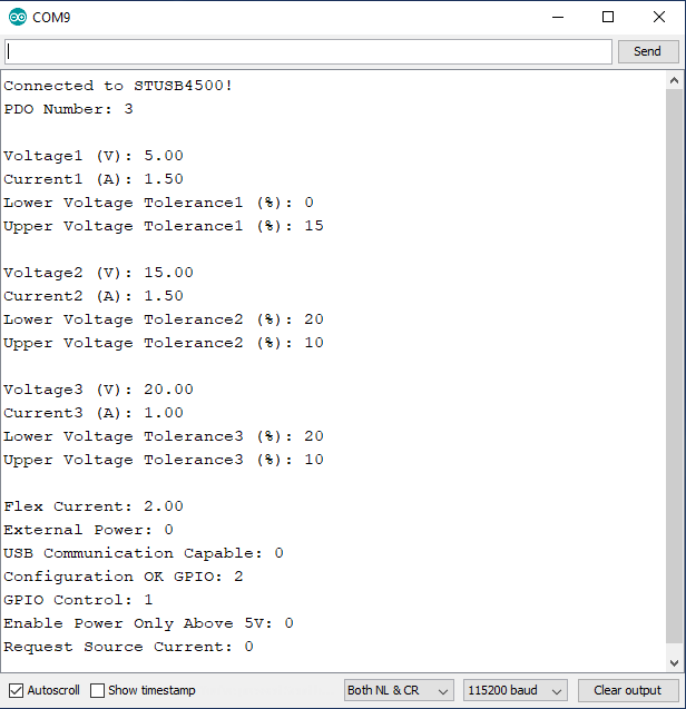
The STUSB4500 is able to store up to three power data objects, or PDOs. Each PDO contains the voltage and current to be requested, along with the voltage tolerance. We can see that the PDO number parameter is set to 3, which means that when we plug in the power adapter, the board will first try to find a power option that matches PDO3, which has a voltage of 20.00V, and maximum current draw of 1.0A. If the power adapter is able to provide at least 1.0A of current at 20.00V, the contract will be accepted by the source and switch to the higher voltage. If the output voltage falls outside of the tolerance window of +10% or -20% (16-22V), the sink controller will disconnect from the source and reset. However, if PDO3 does not match with the source, it will try PDO2's parameters, and if a match is still not made the voltage would stay at 5V.
Flex current is set to 2.00A, but since none of the PDOs have a current set to 0, that value will not be used. We also see that the board is not expecting an external source of power, nor does it expect the source to support USB communication. The Configuration OK GPIOs are set to 2, which will mean that when a source is connected, if the contract for PDO2 or PDO3 is accepted, the LED corresponding to that PDO will turn on. GPIO control is set to 1, which means the GPIO LED is currently configured for error recovery indication. The enable power only above 5V bit is not set, so the output voltage will briefly be at 5V, but will increase after a contract is accepted. Lastly we see that the request source current bit is not set.
Now that we know what the board is configured for, in our next example we'll configure the board based on the capabilities of our power adapter.
Example 2: Setting NVM Values
In this example we'll modify the NVM values. The code listed below is NOT the same as the SetParameters example in Arduino - below we set actual values, whereas the SetParameters example is a template for your future use.
For this example we'll need to use a power delivery source, which is a 87W USB-C Power Adapter made by Apple, but there are plenty of other adapters available that provide a range of voltages. The power adapter should have a label that describes the input and output power capabilities as shown below.
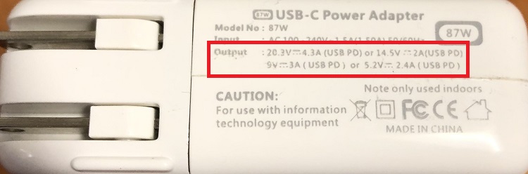
The input power is 100-240 VAC and up to 1.5A of primary current. The output can provide one of the following: 20V/4.3A, or 15V/2A, or 9V/3A, or 5V/2.4A. Based on these options, let's change the voltage to 15V. That voltage option is able to draw up to 2A of current. The current requested can only go up to that value for the power delivery contract to be accepted. The increased voltage of 15.3V instead of 15.0V is labeled based on the actual output voltage, but the source should advertise 15.0V. The increase is to compensate for voltage drop across the cable under heavy current draw. The settings we're going to change though are:
- PDO Number: 3
- PDO3 Voltage: 15.0V
- PDO3 Current: 0.5A
- PDO3 Upper Voltage Tolerance: 20%
- PDO3 Lower Voltage Tolerance: 20%
Copy the code below into your Arduino IDE and upload it to your board. After the code has been uploaded, open your serial port and verify the changes were applied.
language:c
/*
  Writing New Settings to the STUSB4500 Power Delivery Board
  By: Alex Wende
  SparkFun Electronics
  Date: February 6th, 2020
  License: This code is public domain but you buy me a beer if you use this and we meet someday (Beerware license).
  Feel like supporting our work? Buy a board from SparkFun!
  https://www.sparkfun.com/products/15801

  This example demonstrates how to write new NVM settings to the STUSB4500

  Quick-start:
  - Use a SparkFun RedBoard Qwiic -or- attach the Qwiic Shield to your Arduino/Photon/ESP32 or other
  - Upload example sketch
  - Plug the Power Delivery Board onto the RedBoard/shield
  - Open the serial monitor and set the baud rate to 115200
  - The RedBoard will connect to the Power Delivery Board over I2C write the settings:
    * PDO Number: 3
    * PDO3 Voltage: 15.00V
    * PDO3 Current: 0.5A
    * PDO3 Under Voltage Lock Out: 20%
    * PDO3 Over Voltage Lock Out: 20%
  - After the settings are written, the old settings are printed out and then the new settings are printed
*/
// Include the SparkFun STUSB4500 library.
// Click here to get the library: http://librarymanager/All#SparkFun_STUSB4500

#include <Wire.h>
#include <SparkFun_STUSB4500.h>

STUSB4500 usb;

void setup()
{
  Serial.begin(115200);
  Wire.begin(); //Join I2C Bus
  delay(500);

  /* The Power Delivery board uses the default settings with address 0x28 using Wire.

     Opionally, if the address jumpers are modified, or using a different I2C bus,
     these parameters can be changed here. E.g. usb.begin(0x29,Wire1)

     It will return true on success or false on failure to communicate. */
  if(!usb.begin())
  {
    Serial.println("Cannot connect to STUSB4500.");
    Serial.println("Is the board connected? Is the device ID correct?");
    while(1);
  }

  Serial.println("Connected to STUSB4500!");
  delay(100);

  float voltage, current;
  byte lowerTolerance, upperTolerance, pdoNumber;

  pdoNumber = usb.getPdoNumber();
  voltage = usb.getVoltage(3);
  current = usb.getCurrent(3);
  lowerTolerance = usb.getLowerVoltageLimit(3);
  upperTolerance = usb.getUpperVoltageLimit(3);

  /* Since we're going to change PDO3, we'll make sure that the
     STUSB4500 tries PDO3 by setting PDO3 to the highest priority. */
  usb.setPdoNumber(3);

  /* PDO3
   - Voltage 5-20V
   - Current value for PDO3 0-5A, if 0 used, FLEX_I value is used
   - Under Voltage Lock Out (setUnderVoltageLimit) 5-20%
   - Over Voltage Lock Out (setUpperVoltageLimit) 5-20%
  */
  usb.setVoltage(3,15.0);
  usb.setCurrent(3,0.5);
  usb.setLowerVoltageLimit(3,20);
  usb.setUpperVoltageLimit(3,20);

  /*Write and save settings to STUSB4500*/
  usb.write();

  /*Read settings saved to STUSB4500*/
  usb.read();

  Serial.println();

  /*Print old setting*/
  Serial.println("Original Values:");
  Serial.print("PDO Number: ");
  Serial.println(pdoNumber);
  Serial.print("Voltage3 (V): ");
  Serial.println(voltage);
  Serial.print("Current3 (A): ");
  Serial.println(current);
  Serial.print("Lower Voltage Tolerance3 (%): ");
  Serial.println(lowerTolerance);
  Serial.print("Upper Voltage Tolerance3 (%): ");
  Serial.println(upperTolerance);

  Serial.println();

  /*Print new settings*/
  Serial.println("New Values:");
  Serial.print("PDO Number: ");
  Serial.println(usb.getPdoNumber());
  Serial.print("Voltage3 (V): ");
  Serial.println(usb.getVoltage(3));
  Serial.print("Current3 (A): ");
  Serial.println(usb.getCurrent(3));
  Serial.print("Lower Voltage Tolerance3 (%): ");
  Serial.println(usb.getLowerVoltageLimit(3));
  Serial.print("Upper Voltage Tolerance3 (%): ");
  Serial.println(usb.getUpperVoltageLimit(3));
}

void loop()
{
}
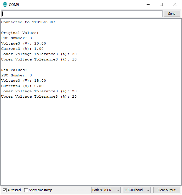
After the code has uploaded, open the serial monitor at 115200 baud and make sure the settings were applied, as shown below.
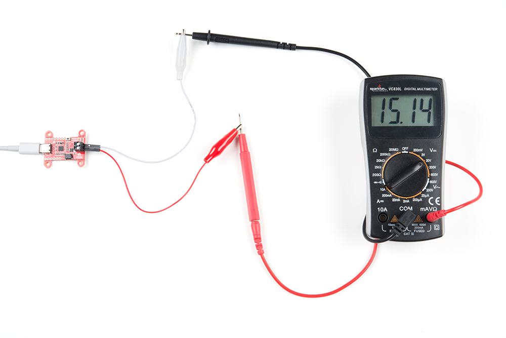
Reset the Power Delivery board and connect the USB-C cable. If the contract was accepted, the yellow LED for PDO3 should be on. With a multimeter, verify the voltage is around 15V as shown below. If the LED turns off, press the reset button and board should switch to the correct voltage.
Example 3: Changing Voltages on the Fly
In this example we will use the soft reset function to force the STUSB4500 to re-negotiate with the power delivery source. Using the same power supply as the previous example, we have 5, 9, 12, 15, and 20V available. If you’re following along from the previous example, the Power Delivery board will initially negotiate for 15V, then the voltage will change to 9V, followed by 12V, and then 5V before looping back to 9V about every three seconds.
Copy the code below into your Arduino IDE and upload to your board, or you can load Example 4-ChangingVoltages from the examples menu for the SparkFun STUSB4500 library.
language:c
/*
  Changing Output Voltage on the Fly
  By: Alex Wende
  SparkFun Electronics
  Date: February 16th, 2021
  License: This code is public domain but you buy me a beer if you use this and we meet someday (Beerware license).
  Feel like supporting our work? Buy a board from SparkFun!
  https://www.sparkfun.com/products/15801

  This example demonstrates how to change the STUSB4500 output voltage without cycling power or pressing the
  reset button for the STUSB4500. Note that the STUSB4500 is not a voltage regulator, the voltages the board is
  capable of outputting are only those supported by the USB-C power adapter connected.

  Quick-start:
  - Use a SparkFun RedBoard Qwiic -or- attach the Qwiic Shield to your Arduino/Photon/ESP32 or other
  - Modify the voltages to match those supported by the power adapter (most common are 5,9,12,15,20V)
  - Upload the sketch
  - Plug the Power Delivery Board onto the RedBoard/shield
  - Open the serial monitor and set the baud rate to 115200
  - The RedBoard will connect to the Power Delivery Board over I2C and print out all of the settings saved.
*/

// Include the SparkFun STUSB4500 library.
// Click here to get the library: http://librarymanager/All#SparkFun_STUSB4500

#include <Wire.h>
#include <SparkFun_STUSB4500.h>

STUSB4500 usb;

void setup()
{
  Serial.begin(115200);
  Wire.begin(); //Join I2C bus

  delay(500);

  /* The Power Delivery board uses the default settings with address 0x28 using Wire.

     Opionally, if the address jumpers are modified, or using a different I2C bus,
     these parameters can be changed here. E.g. usb.begin(0x29,Wire1)

     It will return true on success or false on failure to communicate. */
  if(!usb.begin())
  {
    Serial.println("Cannot connect to STUSB4500.");
    Serial.println("Is the board connected? Is the device ID correct?");
    while(1);
  }

  Serial.println("Connected to STUSB4500!");
  delay(100);

  /* Read the settings saved to the NVM map*/
  usb.read();

  /* Read the Power Data Objects (PDO) highest priority */
  Serial.print("PDO Number: ");
  Serial.println(usb.getPdoNumber());

  /* Read settings for PDO1 */
  Serial.println();
  Serial.print("Voltage1 (V): ");
  Serial.println(usb.getVoltage(1));
  Serial.print("Current1 (A): ");
  Serial.println(usb.getCurrent(1));
  Serial.print("Lower Voltage Tolerance1 (%): ");
  Serial.println(usb.getLowerVoltageLimit(1));
  Serial.print("Upper Voltage Tolerance1 (%): ");
  Serial.println(usb.getUpperVoltageLimit(1));
  Serial.println();

  /* Read settings for PDO2 */
  Serial.print("Voltage2 (V): ");
  Serial.println(usb.getVoltage(2));
  Serial.print("Current2 (A): ");
  Serial.println(usb.getCurrent(2));
  Serial.print("Lower Voltage Tolerance2 (%): ");
  Serial.println(usb.getLowerVoltageLimit(2));
  Serial.print("Upper Voltage Tolerance2 (%): ");
  Serial.println(usb.getUpperVoltageLimit(2));
  Serial.println();

  /* Read settings for PDO3 */
  Serial.print("Voltage3 (V): ");
  Serial.println(usb.getVoltage(3));
  Serial.print("Current3 (A): ");
  Serial.println(usb.getCurrent(3));
  Serial.print("Lower Voltage Tolerance3 (%): ");
  Serial.println(usb.getLowerVoltageLimit(3));
  Serial.print("Upper Voltage Tolerance3 (%): ");
  Serial.println(usb.getUpperVoltageLimit(3));
  Serial.println();

  /* Read the flex current value */
  Serial.print("Flex Current: ");
  Serial.println(usb.getFlexCurrent());

  /* Read the External Power capable bit */
  Serial.print("External Power: ");
  Serial.println(usb.getExternalPower());

  /* Read the USB Communication capable bit */
  Serial.print("USB Communication Capable: ");
  Serial.println(usb.getUsbCommCapable());

  /* Read the POWER_OK pins configuration */
  Serial.print("Configuration OK GPIO: ");
  Serial.println(usb.getConfigOkGpio());

  /* Read the GPIO pin configuration */
  Serial.print("GPIO Control: ");
  Serial.println(usb.getGpioCtrl());

  /* Read the bit that enables VBUS_EN_SNK pin only when power is greater than 5V */
  Serial.print("Enable Power Only Above 5V: ");
  Serial.println(usb.getPowerAbove5vOnly());

  /* Read bit that controls if the Source or Sink device's
     operating current is used in the RDO message */
  Serial.print("Request Source Current: ");
  Serial.println(usb.getReqSrcCurrent());
}

void loop()
{
  /*
   * The output voltage shouldn't change yet. This is because
   * the soft reset function needs to called to take affect.
  */
  Serial.println("\nSet PDO3 to 9V (nothing should happen)");
  usb.setPdoNumber(3); //Make sure PDO3 is set to the highest priority for this example
  usb.setVoltage(3,9.0);
  delay(3000);

  // Now the voltage should change to 9V after calling the softReset function
  Serial.println("Performing a soft reset should now let the voltage change");
  usb.softReset();
  delay(3000);

  // Let's try changing to 12V now
  Serial.println("Setting PDO3 to 12V");
  usb.setVoltage(3,12.0);
  usb.softReset();
  delay(3000);

  /*
   *  Instead of writing a voltage, you can also just change the PDO number,
   *  and then call softReset.
   *
   *  USB PD must be able to support at least 5V. As a result, PDO1 is fixed
   *  at 5V and cannot be changed. Switching to PDO1 is a fast and easy way
   *  swap to 5V without having to set the voltage to 5V.
  */
  Serial.println("Switching to PDO1");
  usb.setPdoNumber(1);
  usb.softReset();
  delay(3000);
}
After the code has been uploaded, open the serial monitor at 115200 baud, and you should see something like this:

The softReset function forces the STUSB4500 to re-negotiate with the source using the values saved in the I2C registers, not the NVM registers. When the voltage is changed in the highest priority PDO register and a soft reset is performed the Power Delivery board re-negotiates with new voltage and current values. If you want to flip between the three different PDO values, you can change the value of the setPdoNumber function instead changing the voltage or current values.
It’s important to mention that these values are not saved to the NVM registers unless the write function is called. So after a hard reset using the reset button or pin, or after a power cycle, the values saved in the NVM registers get copied into the PDO registers.