Power Delivery Board - USB-C (Qwiic) Hookup Guide
 Alex the Giant, Ell C
 Introduction
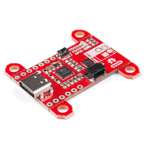
USB Type-C brought two significant changes to the USB standard. The reversible connector eliminated the problem of trying to plug the connector in the right way every time. The second major change was allowing the flexibility to have USB power with an adjustable USB voltage from anywhere between 5V and 20V and up to 100W of power. The SparkFun Power Delivery Board takes advantage of the power delivery standard with the use of a standalone controller from STMicroelectronics, the STUSB4500. The controller does all the heavy lifting of power negotiation and provides an easy way to configure over I2C.
Required Materials
To follow along with this guide, you will need the following materials. You may not need everything, depending on what you have. Add it to your cart, read through the guide, and adjust the cart as necessary.
Additional Tools
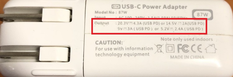
You will also need a USB Type-C power adapter that supports power delivery and a power delivery Type-C cable which has thicker power wires in the cable. This will minimize voltage drops across the cable and heat up less under high current loads. The Power Delivery Board's voltages and available current output are limited by the power delivery adapter used. The cable and power adapter used in this guide is a 87W USB-C Power Adapter made by Apple, and supports 5.2V, 9V, 14.5V, and 20.3V.
Suggested Reading
Before continuing on with this guide, you may want to familiarize yourself with some of these topics if they're unfamiliar to you. If you aren't familiar with the Qwiic system, we recommend reading here for an overview.
| Qwiic Connect System |
If you aren't familiar with the following concepts, we recommend checking out these tutorials before continuing. Make sure to install the appropriate drivers before uploading code. In this case, we'll need to make sure the CH340 driver are installed for the RedBoard Qwiic.
I2C
How to Use a Multimeter
RedBoard Qwiic Hookup Guide
How to Install CH340 Drivers
Hardware Overview
STUSB4500
When it comes to power delivery you have two types of power roles. The first is the provider, also known as the source, which is capable of providing power over the USB power bus. The other role is the consumer, also known as the sink, which draws power from the source.
The STUSB4500 is a USB Type-C and power delivery controller IC for sink applications. The controller is able to negotiate a power delivery contract with a source (ie a power delivery wall wart or power adapter) without the need for an external microcontroller, although you will need a microcontroller to configure the board. With this controller, we are taking advantage of STMicroelectronic's proprietary algorithms and configurable power data objects (PDOs) using integrated non-volatile memory (NVM). Its laundry list of features include:
- "Attach detection" between two USB Type-C ports
- Establish a valid source-to-sink connection
- Negotiate a USB power delivery (PD) contract with a PD capable source
- Monitor the VBUS power path and manage the VBUS voltage transitions
- Manage high voltage protections
- Dual high power charging path support
Understanding how the power negotiation will be covered in the USB-C Power Negotiation section, but for right now, let's go over the board itself.
Power
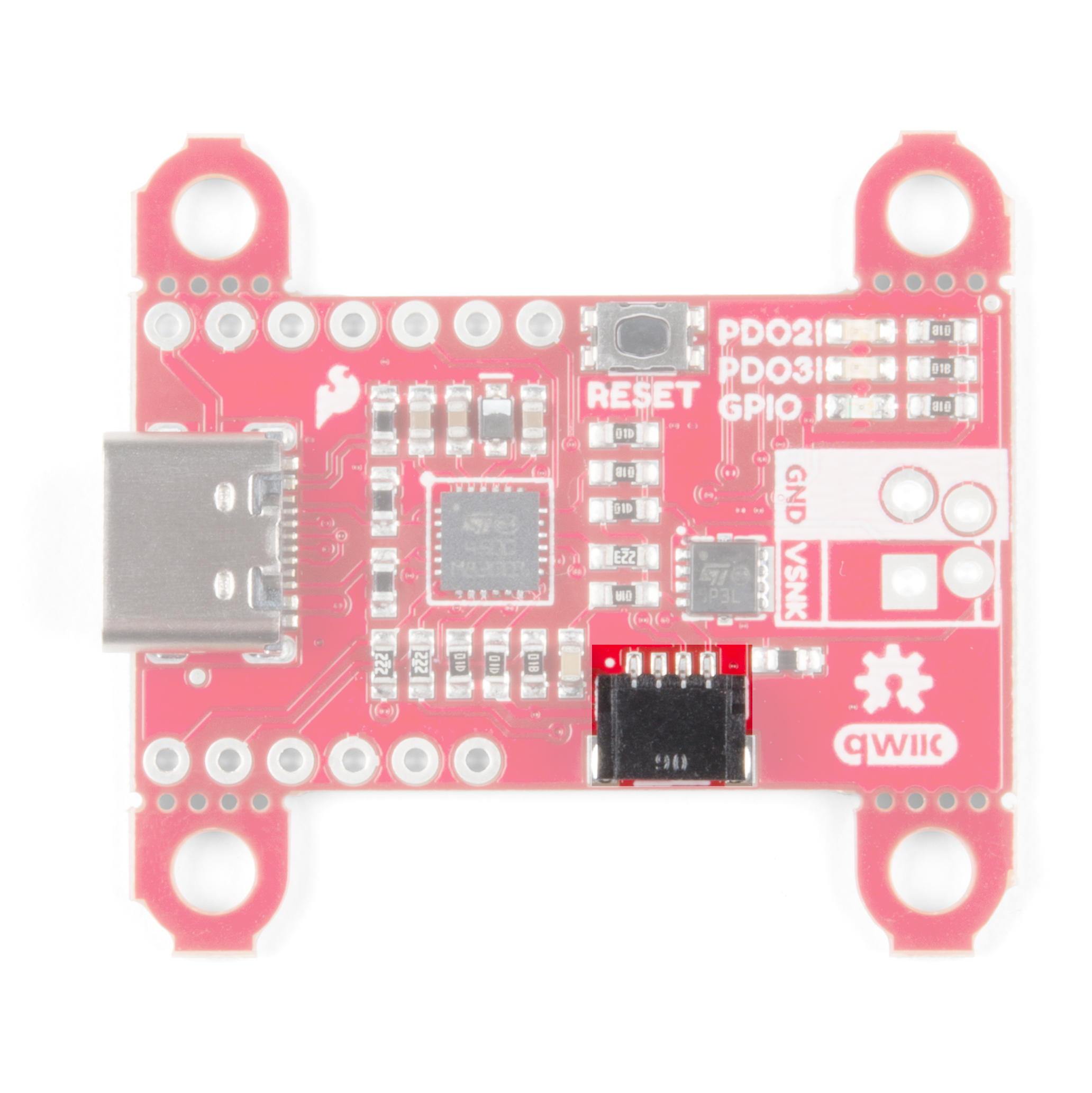
The Power Delivery board can be powered in one of two ways, either through the USB Type-C connector, or with 3.3V from the Qwiic Connector if you just need to configure a new power delivery profile.
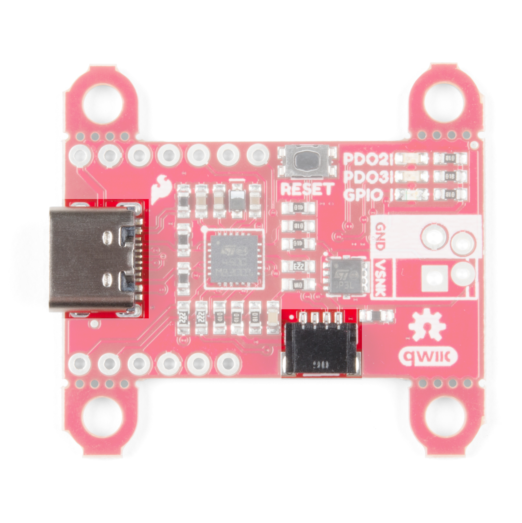
I2C Pins
To configure the board, you will need an I2C bus. The Qwiic system makes it easy to connect the Power Delivery board to a microcontroller to set the NVM parameters to power your project via the Qwiic connector. Depending on your application, you can also connect to the I2C bus via the plated through holes for SDA and SCL.
 |
 |
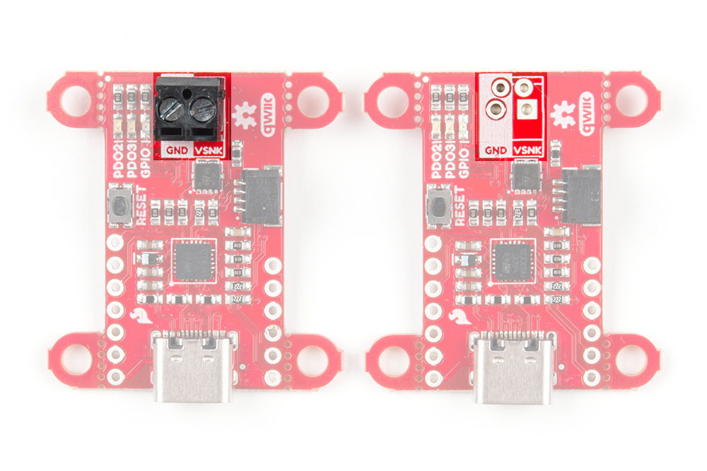
| Top View | Bottom View |
Pins
The board breaks out the following pins:
| Pin Name | Description |
|---|---|
| VIN | This is the input power pin, which is connected to VBUS on the Type-C connector. |
| VSNK | Power output enabled after successful power negotiation |
| VDD | Optional logic power input, 3.0V - 5.5V |
| GND | Ground |
| SCL | I2C clock input |
| SDA | I2C data input/output |
| D- | USB 2.0 differential pair, negative |
| D+ | USB 2.0 differential pair, positive |
| Alert | I2C interrupt, active low open drain |
| Reset | Reset input, active high |
| GPIO | General purpose output, active low open drain |
| PDO2 | Power contract flag for PDO2, active low open drain |
| PDO3 | Power contract flag for PDO3, active low open drain |

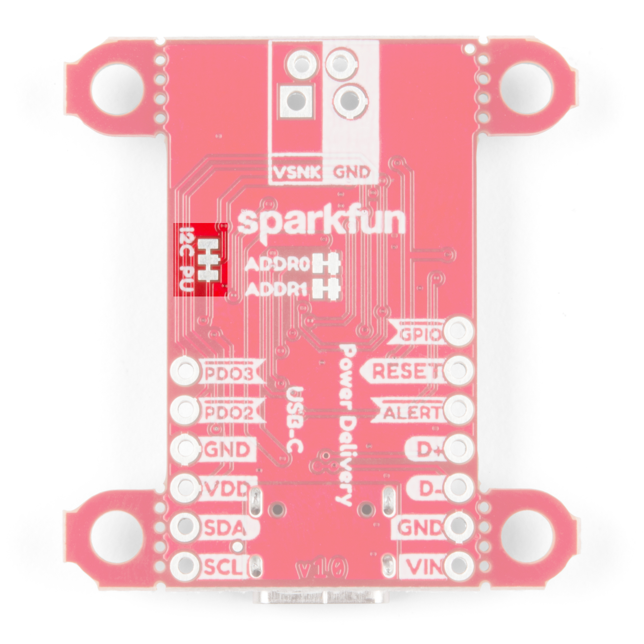
Jumpers
The board has a few jumper pads to configure the I2C bus.
How to Work with Jumper Pads and PCB Traces
Address Select
The default address of the board is 0x28. If you need to adjust the address of the board, you can cut one or both of the address pads labels ADDR0 and ADDR1.
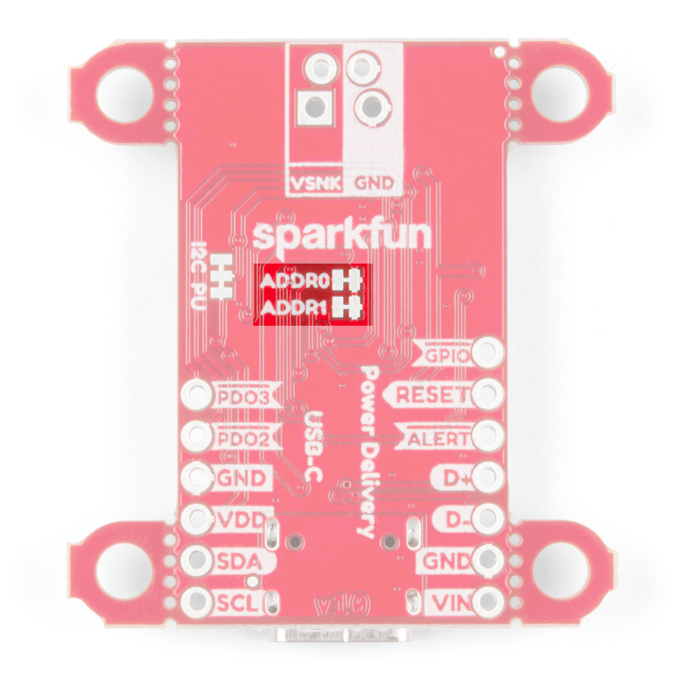
The table below lists the four jumper configurations along with the corresponding hexadecimal device address.
| ADDR0 | ADDR1 | Device Address |
|---|---|---|
| Closed | Closed | 0x28 (default) |
| Open | Closed | 0x29 |
| Closed | Open | 0x2A |
| Open | Open | 0x2B |
Pull-Up Resistors
The board also includes jumpers to disable the pull-up resistors on the I2C bus. If you are using a few I2C devices on the same bus that already have pull-up resistors on their board, you may want to cut the jumpers to disconnect these pull-up resistors. The Power Delivery board utilizes non-volatile memory, the settings saved to device stay configured even if it loses power, so the only time this board needs to be connected over I2C is to modify the NVM parameters.
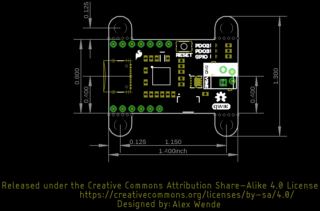
Dimensions
USB-C Power Negotiation
Power Data Objects (PDOs)
The STUSB4500 has a set of user defined parameters that can be customized using the NVM re-programming through the I2C interface. This allows for changing the preset configuration of the power delivery interface and define new configurations based on specific application requirements.
On power-up, or after a hard reset, the NVM parameters are copied into the I2C registers and used by the controller during the system operation. After a soft reset, the controller will use the values saved in I2C registers to re-negotiate with the source. The controller can store up to three PDOs, with PDO3 having the highest priority and PDO1 having the lowest. After the NVM parameters have been copied to the I2C registers, the STUSB4500 will ask the source for it's capabilities to find a PDO match.
Each PDO has four parameters as shown in the table below:
| Parameter | Value Range | Notes |
|---|---|---|
| Voltage | 5 - 20 (V) | PDO1 is fixed at 5V and cannot be changed. |
| Over Voltage Tolerance | 5 - 20 (%) | Sets the upper voltage tolerance. For example, say this parameter is set to 5% and the voltage is set to 9V. If the supply voltage goes above 9.45V, the output (VSNK) will turn off. |
| Under Voltage Tolerance | 5 - 20 (%) | Sets the lower voltage tolerance for PDO2 and PDO3 only. For example, say this parameter is set to 5%, and the voltage is set to 9V. If the supply voltage drops below 8.55V, the output (VSNK) will turn off. PDO1 has a fixed under voltage limit of 3.3V and cannot be changed. |
| Current | 0 - 5 (A) | 16 possible values, see setCurrent function in Arduino Library secton for exact values. |
Each source might have a slightly different voltages listed on the case. One charger might advertise 12V, while another might advertise 12.3V perhaps to compensate for voltage drop across the cable, while another might say 11.5V to indicate the voltage at the end of the cable under the full load. Most sources though will advertise some combination of 5V, 9V, 12V, 15V, or 20V when negotiating with the consumer.
The current should be the maximum amount of current that the Power Delivery board expects to draw from the source. The STUSB4500 is not able to measure the actual current draw and will allow as much current as the source is able to deliver. If the current parameter is less than or equal to the max current the source advertised, the controller will send a request to source for that power profile. If the voltage or current parameters do not match with one of the capabilities of the source, the controller will try the next PDO to find a match with the source.
If the source accepts the contract, the source will switch from the defaulted VBUS voltage of 5V, to the voltage that was requested, and the VBUS_EN_SINK pin will be pulled low, and enable current to flow through the MOSFET which controls power to the VSNK power output pin.
Power Delivery Contract between Source and Sink
With the "U" in USB standing for Universal, when two devices are connected there are a bunch of messages sent between them to figure out what each device is connected to, and what each device supports. For the sake of simplicity, we're only going to look at the power delivery contract from a high level to understand what's going on.

Of the 24 pins of the USB Type-C connector (shown above), the STUSB4500 only connects directly to 10 of these: 4 pins are used for VBUS, another 4 pins to ground, and the 2 channel configuration, or CC, pins. Depending on the cable orientation, one of these CC pins is used to send and receive messages between the sink and source. When a sink device connects to a source, the voltage on the VBUS starts off at 5V, just like the old USB standard.
Shortly after the source and sink are connected, the source will advertise it's capabilities as a power source, such as 5V@3A, 9V@2A, and any other power delivery options it's capable of. After that message is received, the controller will look at the PDO options available to find a match. Upon a match, the controller will ask for one of the voltage and current options. After the source accepts, the voltage is then switched to the voltage requested.
To find a match, the STUSB4500 controller first looks at the SNK_PDO_NUMB parameter, which is an integer value between 1 and 3, which corresponds to the highest priority PDO number. If the SNK_PDO_NUMB has a value of 3, it will first check to see if the source is able to provide PDO3, if not it will check PDO2, followed by PDO1. If SNK_PDO_NUMB has a value of 2, it will start by checking PDO2, followed by PDO1, and ignore PDO3. Finally if SNK_PDO_NUMB has a value of 1, it will only check PDO1. The two values the controller looks at to find a match are the voltage and current. As previously mentioned, most of the power delivery adapters will have a combination of 5V, 9V, 12V, 15V, and 20V. The packaging might say 5.2V or 20.3V, but in the capabilities message they'll actually specify 5V or 20V.
The other portion of the contract is the current being requested. If the voltage is accepted, but is only capable of delivering 1.5A of current at that voltage, but 2.0A of current was requested, that contract will be rejected by the source even though the source was capable of supplying that voltage. Alternatively, requesting 0.5A of current with a source capable of delivering 1.5A will be accepted. The amount of current requested should be about is expected for the project, but the source will allow the sink to draw more current than requested, up to the limit of that power delivery option.
Hardware Hookup
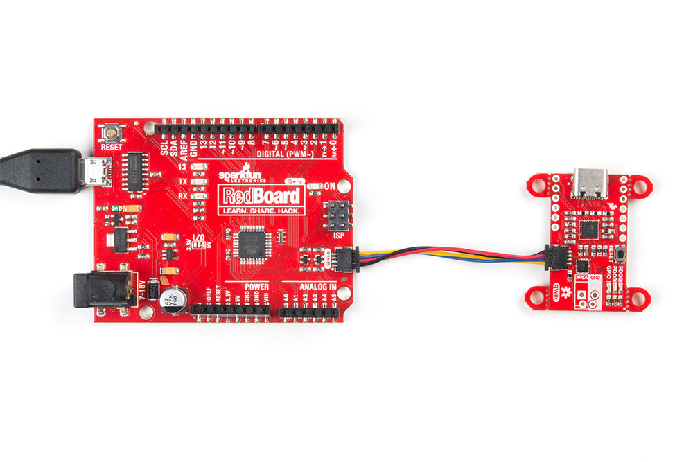
This is an I2C based board, which allows us to include a Qwiic connector on the breakout board. Hooking up the device is easy, just plug one end of the Qwiic cable into the Power Delivery board and the other to your development board. In this case it's the RedBoard Qwiic.
How to Install CH340 Drivers
Suppling power to your project can be accomplished in couple of ways. The board provides breadboard friendly 0.1 inch spacing, along with 3.5mm screw terminal spacing. If you're new to soldering, refer to our How To Solder Tutorial.
After the board has been configured, the Qwiic connector can be removed, and the board will remember the settings even after power is disconnected. With those connections out of the way, it's time to configure the board!
Arduino Library
SparkFun has written a library to control the Power Delivery board for the STUSB4500. You can obtain this library through the Arduino Library Manager. By searching for STUSB4500, you should see one written by SparkFun Electronics and you should be able to install the latest version. If you prefer downloading libraries manually, you can grab them from the GitHub Repository.
Functions
The library has a ton of functions available for reading each of the NVM parameters for the Power Delivery board. Below is a list of the functions available along with a description of what each function does and how to use it.
uint8_t begin( uint8_t deviceAddress, TwoWire &wirePort ) - Call at the beginning of the sketch to initialize the device. This function takes two optional parameters: deviceAddress and wirePort. This function will return
truewhen the device is intialized, andfalseif it is unable to communicate with the device.wirePort - By default, the library uses the standard Wire bus, but if your board has multiple I2C buses, you can define Wire1 here.
deviceAddress - If both of the address jumpers on the back of the board are closed, this parameter does not need to be provided. Otherwise, you can use the table below to get the I2C address of the Power Delivery Board.
| ADDR0 | ADDR1 | Device Address |
|---|---|---|
| Closed | Closed | 0x28 (default) |
| Open | Closed | 0x29 |
| Closed | Open | 0x2A |
| Open | Open | 0x2B |
void read( void ) - This function reads the NVM parameters and loads them into memory. This function is called in the
begin()function, and shouldn't need to be called in your program.void write( uint8_t defaultVals ) - This function writes the NVM parameters to the STUSB4500. After all of the parameters have been changed, calling this function will save the parameters to the device. This function takes an optional argument of
DEFAULT. When DEFAULT is passed to the write function, the default NVM parameters are written to the device.void softReset( void ) - This function performs a soft reset of the STUSB4500. After a soft reset power is re-negotiated with the source using the values loaded in the PDO registers. To see this function in use, refer to Example4-ChangingVoltages in the Arduino library, or the “Changing Voltages on the Fly” example below.
float getVoltage( uint8_t pdo_numb ) - Returns the voltage requested for the PDO number (1-3).
float getCurrent( uint8_t pdo_numb ) - Returns the current requested for the PDO number (1-3).
uint8_t getLowerVoltageLimit( uint8_t pdo_numb ) - Returns the under voltage lockout parameter for the PDO number (1-3). PDO1 has a fixed value that cannot be changed and will always return 0. The under voltage limit is fixed at 3.3V. PDO2 and PDO3 will return a value between 5% and 20%.
uint8_t getUpperVoltageLimit( uint8_t pdo_numb ) - Returns the over voltage lockout parameter for the PDO number (1-3). The value returned will be between 5% and 20%.
float getFlexCurrent( void ) - Return the value for the flex current parameter, which is a global variable common to all PDOs. Refer to
setFlexCurrentfunction for more information on how to use flex current.uint8_t getPdoNumber( void ) - Returns value saved in memory for the highest priority PDO number (1-3).
uint8_t getExternalPower( void ) - Returns the value for the SNK_UNCONS_POWER parameter (0 or 1). SNK_UNCONS_POWER is the unconstrained power bit setting in capabilities message sent by the sink. A 0 means there is no external source of power (default), and a 1 means an external source of power is available and is sufficient to adequately power the system while charging external devices.
uint8_t getUsbCommCapable( void ) - Returns the value for the USB_COMM_CAPABLE parameter (0 or 1). USB_COMM_CAPABLE refers to USB2.0 or 3.x data communication capability by the sink system. A 0 means the sink device does not support data communication (default). A 1 means that the sink does support data communication.
uint8_t getConfigOkGpio( void ) - Returns the POWER_OK_CFG parameter value (0-3), which controls the behavior of the VBUS_EN_SNK, POWER_OK2, and POWER_OK3 pins. Refer to the
setConfigOKGPIOfunction for more information.- 0 - Configuration 1
- 1 - Not applicable
- 2 - Configuration 2 (default)
- 3 - Configuration 3
uint8_t getGpioCtrl( void ) - Returns the behavior setting for the GPIO pin (0-3). Refer to the
setGpioCtrlfunction for more information.- 0 - Software controlled GPIO
- 1 - Error recovery
- 2 - Debug
- 3 - Sink power
uint8_t getPowerAbove5vOnly( void ) - Returns the POWER_ONLY_ABOVE_5V parameter (0 or 1). If 0 is returned, the output will be enabled when the source is attached, regardless of the voltage. If 1 is returned, the output will be enabled only when the source is attached and VBUS voltage is negotiated to PDO2 or PDO3.
void setPdoNumber( uint8_t pdo_numb ) - Takes the parameter pdo_numb (1-3). There are three Power Data Objects (PDO) that the Power Delivery board can store. PDO3 has the highest priority, followed by PDO2, and finally PDO1. This function declares which of the three PDOs should be negotiated first. For example, if setPdoNumber is set to 3, PDO3 will be negotiated first, followed by PDO2 if a contract is not made, and finally PDO1 if PDO2 fails as well. If setPdoNumber is set to 2, PDO3 will be ignored and PDO2 will be negotiated, followed by PDO1. Lastly if setPdoNumber is set to 1, only PDO1 will be negotiated.
void setVoltage( uint8_t pdo_numb, float voltage ) - Takes two parameters: pdo_numb (1-3), and voltage (10-bit resolution). PDO1 is fixed at 5V and cannot be changed. PDO2 and PDO3 can be any voltage up to 20V.
- The PDO3 has the highest priority and PDO1 has the lowest priority, starting at the number defined in the
setPdoNumber()parameter. The source controls the voltage present on VBUS, or in the case of the Power Delivery board, VIN. Common voltages available from sources are: 5V, 9V, 12V, 15V, and 20V.
- The PDO3 has the highest priority and PDO1 has the lowest priority, starting at the number defined in the
void setCurrent( uint8_t pdo_numb, float current ) - Takes two parameters: pdo_numb (1-3), and current (16 values). The current values are: 0 (Flex Current), 0.5A, 0.75A, 1.0A, 1.25A, 1.50A, 1.75A, 2.0A, 2.25A. 2.50A, 2.75A, 3.0A, 3.5A, 4.0A, 4.5A, and 5.0A.
- The current value should be the amount that the source should be expected to output. If the current is higher than the source is able to provide, the contract will be rejected and the next PDO contract will be negotiated. The Power Delivery board will sink more current than negotiated if the source is able deliver it, but it's recommended to provide the maximum amount of current the project is expected to draw.
setFlexCurrent( float value ) - Takes a float value to set the current common to all PDOs. This value is only used in the power negotiation if the setCurrent value for that PDO is set to 0. The flex current has a resolution of 10mA. Just like the
setCurrentfunction, the current value should be the amount that the source should be expected to deliver. If the current is higher than the source is able to provide, the contract will be rejected and the next PDO contract will be negotiated.setLowerVoltageLimit (uint8_t pdo_numb, uint8_t value ) - Takes two parameters: pdo_numb (2-3), and a integer value (5-20%). Only PDO2 and PDO3 can be changed as PDO1 has a fixed value of 3.3V. In combination with the
setUpperVoltageLimitfunction, this is used to define an acceptable window for the voltage output.- For example if the Power Delivery board requests 15V and has a under voltage tolerance of 5%, the controller will disable the output of the Power Delivery board if the voltage drops below 14.25V, which is 5% of 15V.
setUpperVoltageLimit( uint8_t pdo_numb, uint8_t value ) - Takes two parameters: pdo_numb (1-3), and a integer value (5-20%). In combination with the
setLowerVoltageLimitfunction, this is used to define an acceptable window for the voltage output.- For example if the Power Delivery board requests 15V and has a over voltage tolerance of 5%, the controller will disable the output of the Power Delivery board if the voltage exceeds 15.75V, which is 5% of 15V.
setExternalPower( uint8_t value ) - Takes an integer value (0 or 1). Setting to 0, there is no external source of power. Setting to 1, means there is an external power source available, and is sufficient to adequately power the system while charging external devices.
setUsbCommCapable( uint8_t value ) - Takes an integer value (0 or 1). Setting to 0, there sink does not support data communication. Setting to 1, means the sink does support data communication.
setConfigOkGpio( uint8_t value ) - Takes an integer value (0-3):
- 0 - Configuration 1
- 1 - Not applicable
- 2 - Configuration 2 (default)
- 3 - Configuration 3
| Pin | State |
Description | |
|---|---|---|---|
| Configuration1 | VBUS_EN_SNK | Hi-Z | No Source Attached |
| 0 | Source Attached | ||
| POWER_OK2 | Hi-Z | No functionality | |
| POWER_OK3 | Hi-Z | No functionality | |
| Configuration2 | VBUS_EN_SNK | Hi-Z | No Source Attached |
| 0 | Source Attached | ||
| POWER_OK2 | Hi-Z | No explicit PD contract | |
| 0 | PD explicit contract with PDO2 | ||
| POWER_OK3 | Hi-Z | No explicit PD contract | |
| 0 | PD explicit contract with PDO3 | ||
| Configuration3 | VBUS_EN_SNK | Hi-Z | No Source Attached |
| 0 | Source Attached | ||
| POWER_OK2 | Hi-Z | No source attached or source supplies default USB Type-C current at 5V when source attached. | |
| 0 | Source supplies 3.0A USB Type-C current at 5V when source is attached. | ||
| POWER_OK3 | Hi-Z | No source attached or source supplies default USB Type-C current at 5V when source attached. | |
| 0 | Source supplies 1.5A USB Type-C current at 5V when source is attached. |
*
- setGpioCtrl( uint8_t value ) - Takes an integer value (0-3) to control the GPIO pin (active LOW).
| Value | GPIO Function | Function | Value | Description |
|---|---|---|---|---|
| 0 | Software Controlled GPIO | The output state is controlled by the value stored in bit-0 of I2C register 0x2D | Hi-Z | When the value of bit-0 is 0 (default at start-up) |
| 0 | When the value of bit-0 is 1 | |||
| 1 | Error Recovery | Hardware fault detection such as over temperature, over voltage on the CC pins, or after a hard reset | Hi-Z | No hardware fault detected |
| 0 | Hardware fault detected | |||
| 2 | Debug | Debug accessory detection (Refer to section 3.8 of datasheet for more information) | Hi-Z | No debug accessory detected |
| 0 | Debug accessory detected | |||
| 3 | Sink Power | Indicates USB Type-C current capability advertised by the source | Hi-Z | Source supplies default or 1.5A USB Type-C current at 5V |
| 0 | Source supplies 3.0A USB Type-C current at 5V |
*
setPowerAbove5vOnly( uint8_t value ) - Takes an integer value (0 or 1). Setting to 0, the output is enabled regardless of the of the negotiated voltage. When set to 1, the output is enabled only when the source is attached, and the voltage is negotiated for PDO2 or PDO3.
setReqSrcCurrent( uint8_t value ) - Takes an integer value (0 or 1). Setting to 0 requests the sink current as operating current in the RDO message. Setting to 1 requests the source current as operating current in the RDO message.
Arduino Library Examples
In these examples, we'll connect our Power Delivery board to a RedBoard Qwiic using a Qwiic cable. The Type-C power adapter used in these examples is an Apple 87W USB-C Power Adapter which has an output of 20.3V/4.3A, or 14.5V/2A, or 9V/3A, or 5.2V/2.4A.
Example 1: Reading the NVM Values
In this first example we'll see what settings are currently saved in the board. For this example you don't need to connect to your USB cable, the only connection needed is VDD, GND, SCL, and SDA (which the Qwiic cable will provide).
After the library has been installed, access the first example from your Arduino menu by clicking on: File > Examples > SparkFun STUSB4500 > Example1-ReadParameters. Select your board (in this case Arduino Uno) and COM port that the board enumerated to. Hit the upload button. Open the serial monitor at 115200 baud to see what the current settings are.
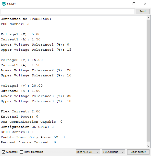
The STUSB4500 is able to store up to three power data objects, or PDOs. Each PDO contains the voltage and current to be requested, along with the voltage tolerance. We can see that the PDO number parameter is set to 3, which means that when we plug in the power adapter, the board will first try to find a power option that matches PDO3, which has a voltage of 20.00V, and maximum current draw of 1.0A. If the power adapter is able to provide at least 1.0A of current at 20.00V, the contract will be accepted by the source and switch to the higher voltage. If the output voltage falls outside of the tolerance window of +10% or -20% (16-22V), the sink controller will disconnect from the source and reset. However, if PDO3 does not match with the source, it will try PDO2's parameters, and if a match is still not made the voltage would stay at 5V.
Flex current is set to 2.00A, but since none of the PDOs have a current set to 0, that value will not be used. We also see that the board is not expecting an external source of power, nor does it expect the source to support USB communication. The Configuration OK GPIOs are set to 2, which will mean that when a source is connected, if the contract for PDO2 or PDO3 is accepted, the LED corresponding to that PDO will turn on. GPIO control is set to 1, which means the GPIO LED is currently configured for error recovery indication. The enable power only above 5V bit is not set, so the output voltage will briefly be at 5V, but will increase after a contract is accepted. Lastly we see that the request source current bit is not set.
Now that we know what the board is configured for, in our next example we'll configure the board based on the capabilities of our power adapter.
Example 2: Setting NVM Values
In this example we'll modify the NVM values. The code listed below is NOT the same as the SetParameters example in Arduino - below we set actual values, whereas the SetParameters example is a template for your future use.
For this example we'll need to use a power delivery source, which is a 87W USB-C Power Adapter made by Apple, but there are plenty of other adapters available that provide a range of voltages. The power adapter should have a label that describes the input and output power capabilities as shown below.
The input power is 100-240 VAC and up to 1.5A of primary current. The output can provide one of the following: 20V/4.3A, or 15V/2A, or 9V/3A, or 5V/2.4A. Based on these options, let's change the voltage to 15V. That voltage option is able to draw up to 2A of current. The current requested can only go up to that value for the power delivery contract to be accepted. The increased voltage of 15.3V instead of 15.0V is labeled based on the actual output voltage, but the source should advertise 15.0V. The increase is to compensate for voltage drop across the cable under heavy current draw. The settings we're going to change though are:
- PDO Number: 3
- PDO3 Voltage: 15.0V
- PDO3 Current: 0.5A
- PDO3 Upper Voltage Tolerance: 20%
- PDO3 Lower Voltage Tolerance: 20%
Copy the code below into your Arduino IDE and upload it to your board. After the code has been uploaded, open your serial port and verify the changes were applied.
language:c
/*
  Writing New Settings to the STUSB4500 Power Delivery Board
  By: Alex Wende
  SparkFun Electronics
  Date: February 6th, 2020
  License: This code is public domain but you buy me a beer if you use this and we meet someday (Beerware license).
  Feel like supporting our work? Buy a board from SparkFun!
  https://www.sparkfun.com/products/15801

  This example demonstrates how to write new NVM settings to the STUSB4500

  Quick-start:
  - Use a SparkFun RedBoard Qwiic -or- attach the Qwiic Shield to your Arduino/Photon/ESP32 or other
  - Upload example sketch
  - Plug the Power Delivery Board onto the RedBoard/shield
  - Open the serial monitor and set the baud rate to 115200
  - The RedBoard will connect to the Power Delivery Board over I2C write the settings:
    * PDO Number: 3
    * PDO3 Voltage: 15.00V
    * PDO3 Current: 0.5A
    * PDO3 Under Voltage Lock Out: 20%
    * PDO3 Over Voltage Lock Out: 20%
  - After the settings are written, the old settings are printed out and then the new settings are printed
*/
// Include the SparkFun STUSB4500 library.
// Click here to get the library: http://librarymanager/All#SparkFun_STUSB4500

#include <Wire.h>
#include <SparkFun_STUSB4500.h>

STUSB4500 usb;

void setup()
{
  Serial.begin(115200);
  Wire.begin(); //Join I2C Bus
  delay(500);

  /* The Power Delivery board uses the default settings with address 0x28 using Wire.

     Opionally, if the address jumpers are modified, or using a different I2C bus,
     these parameters can be changed here. E.g. usb.begin(0x29,Wire1)

     It will return true on success or false on failure to communicate. */
  if(!usb.begin())
  {
    Serial.println("Cannot connect to STUSB4500.");
    Serial.println("Is the board connected? Is the device ID correct?");
    while(1);
  }

  Serial.println("Connected to STUSB4500!");
  delay(100);

  float voltage, current;
  byte lowerTolerance, upperTolerance, pdoNumber;

  pdoNumber = usb.getPdoNumber();
  voltage = usb.getVoltage(3);
  current = usb.getCurrent(3);
  lowerTolerance = usb.getLowerVoltageLimit(3);
  upperTolerance = usb.getUpperVoltageLimit(3);

  /* Since we're going to change PDO3, we'll make sure that the
     STUSB4500 tries PDO3 by setting PDO3 to the highest priority. */
  usb.setPdoNumber(3);

  /* PDO3
   - Voltage 5-20V
   - Current value for PDO3 0-5A, if 0 used, FLEX_I value is used
   - Under Voltage Lock Out (setUnderVoltageLimit) 5-20%
   - Over Voltage Lock Out (setUpperVoltageLimit) 5-20%
  */
  usb.setVoltage(3,15.0);
  usb.setCurrent(3,0.5);
  usb.setLowerVoltageLimit(3,20);
  usb.setUpperVoltageLimit(3,20);

  /*Write and save settings to STUSB4500*/
  usb.write();

  /*Read settings saved to STUSB4500*/
  usb.read();

  Serial.println();

  /*Print old setting*/
  Serial.println("Original Values:");
  Serial.print("PDO Number: ");
  Serial.println(pdoNumber);
  Serial.print("Voltage3 (V): ");
  Serial.println(voltage);
  Serial.print("Current3 (A): ");
  Serial.println(current);
  Serial.print("Lower Voltage Tolerance3 (%): ");
  Serial.println(lowerTolerance);
  Serial.print("Upper Voltage Tolerance3 (%): ");
  Serial.println(upperTolerance);

  Serial.println();

  /*Print new settings*/
  Serial.println("New Values:");
  Serial.print("PDO Number: ");
  Serial.println(usb.getPdoNumber());
  Serial.print("Voltage3 (V): ");
  Serial.println(usb.getVoltage(3));
  Serial.print("Current3 (A): ");
  Serial.println(usb.getCurrent(3));
  Serial.print("Lower Voltage Tolerance3 (%): ");
  Serial.println(usb.getLowerVoltageLimit(3));
  Serial.print("Upper Voltage Tolerance3 (%): ");
  Serial.println(usb.getUpperVoltageLimit(3));
}

void loop()
{
}
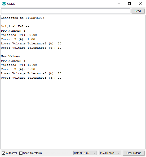
After the code has uploaded, open the serial monitor at 115200 baud and make sure the settings were applied, as shown below.
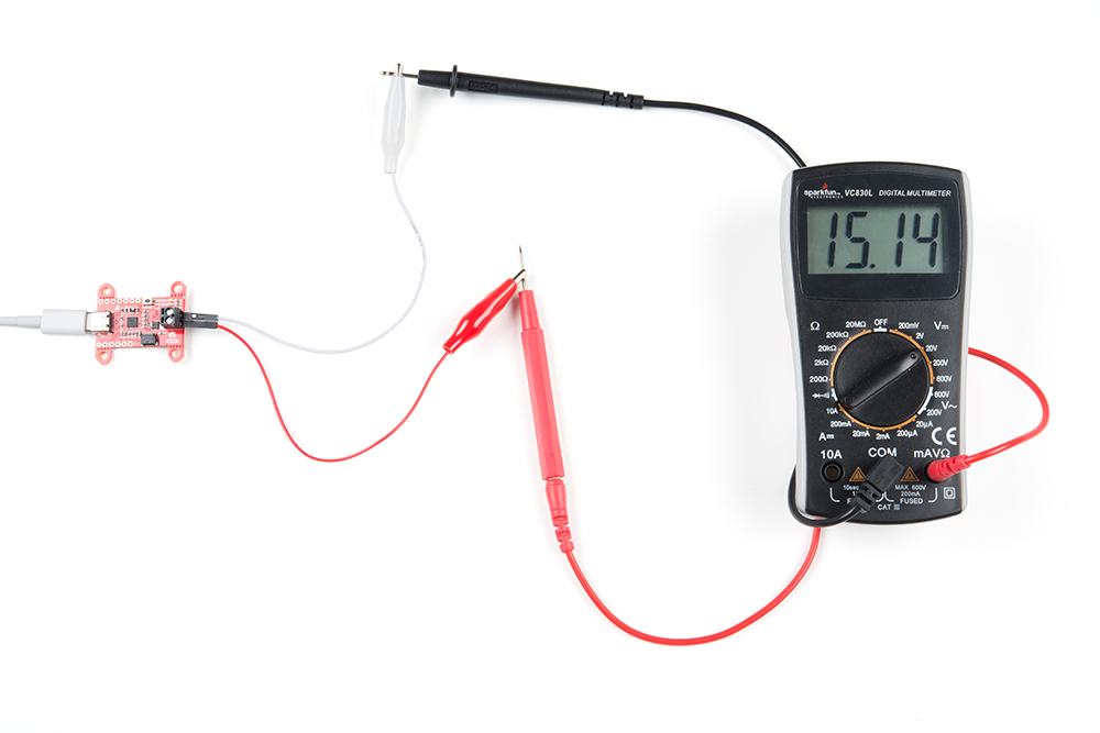
Reset the Power Delivery board and connect the USB-C cable. If the contract was accepted, the yellow LED for PDO3 should be on. With a multimeter, verify the voltage is around 15V as shown below. If the LED turns off, press the reset button and board should switch to the correct voltage.
Example 3: Changing Voltages on the Fly
In this example we will use the soft reset function to force the STUSB4500 to re-negotiate with the power delivery source. Using the same power supply as the previous example, we have 5, 9, 12, 15, and 20V available. If you’re following along from the previous example, the Power Delivery board will initially negotiate for 15V, then the voltage will change to 9V, followed by 12V, and then 5V before looping back to 9V about every three seconds.
Copy the code below into your Arduino IDE and upload to your board, or you can load Example 4-ChangingVoltages from the examples menu for the SparkFun STUSB4500 library.
language:c
/*
  Changing Output Voltage on the Fly
  By: Alex Wende
  SparkFun Electronics
  Date: February 16th, 2021
  License: This code is public domain but you buy me a beer if you use this and we meet someday (Beerware license).
  Feel like supporting our work? Buy a board from SparkFun!
  https://www.sparkfun.com/products/15801

  This example demonstrates how to change the STUSB4500 output voltage without cycling power or pressing the
  reset button for the STUSB4500. Note that the STUSB4500 is not a voltage regulator, the voltages the board is
  capable of outputting are only those supported by the USB-C power adapter connected.

  Quick-start:
  - Use a SparkFun RedBoard Qwiic -or- attach the Qwiic Shield to your Arduino/Photon/ESP32 or other
  - Modify the voltages to match those supported by the power adapter (most common are 5,9,12,15,20V)
  - Upload the sketch
  - Plug the Power Delivery Board onto the RedBoard/shield
  - Open the serial monitor and set the baud rate to 115200
  - The RedBoard will connect to the Power Delivery Board over I2C and print out all of the settings saved.
*/

// Include the SparkFun STUSB4500 library.
// Click here to get the library: http://librarymanager/All#SparkFun_STUSB4500

#include <Wire.h>
#include <SparkFun_STUSB4500.h>

STUSB4500 usb;

void setup()
{
  Serial.begin(115200);
  Wire.begin(); //Join I2C bus

  delay(500);

  /* The Power Delivery board uses the default settings with address 0x28 using Wire.

     Opionally, if the address jumpers are modified, or using a different I2C bus,
     these parameters can be changed here. E.g. usb.begin(0x29,Wire1)

     It will return true on success or false on failure to communicate. */
  if(!usb.begin())
  {
    Serial.println("Cannot connect to STUSB4500.");
    Serial.println("Is the board connected? Is the device ID correct?");
    while(1);
  }

  Serial.println("Connected to STUSB4500!");
  delay(100);

  /* Read the settings saved to the NVM map*/
  usb.read();

  /* Read the Power Data Objects (PDO) highest priority */
  Serial.print("PDO Number: ");
  Serial.println(usb.getPdoNumber());

  /* Read settings for PDO1 */
  Serial.println();
  Serial.print("Voltage1 (V): ");
  Serial.println(usb.getVoltage(1));
  Serial.print("Current1 (A): ");
  Serial.println(usb.getCurrent(1));
  Serial.print("Lower Voltage Tolerance1 (%): ");
  Serial.println(usb.getLowerVoltageLimit(1));
  Serial.print("Upper Voltage Tolerance1 (%): ");
  Serial.println(usb.getUpperVoltageLimit(1));
  Serial.println();

  /* Read settings for PDO2 */
  Serial.print("Voltage2 (V): ");
  Serial.println(usb.getVoltage(2));
  Serial.print("Current2 (A): ");
  Serial.println(usb.getCurrent(2));
  Serial.print("Lower Voltage Tolerance2 (%): ");
  Serial.println(usb.getLowerVoltageLimit(2));
  Serial.print("Upper Voltage Tolerance2 (%): ");
  Serial.println(usb.getUpperVoltageLimit(2));
  Serial.println();

  /* Read settings for PDO3 */
  Serial.print("Voltage3 (V): ");
  Serial.println(usb.getVoltage(3));
  Serial.print("Current3 (A): ");
  Serial.println(usb.getCurrent(3));
  Serial.print("Lower Voltage Tolerance3 (%): ");
  Serial.println(usb.getLowerVoltageLimit(3));
  Serial.print("Upper Voltage Tolerance3 (%): ");
  Serial.println(usb.getUpperVoltageLimit(3));
  Serial.println();

  /* Read the flex current value */
  Serial.print("Flex Current: ");
  Serial.println(usb.getFlexCurrent());

  /* Read the External Power capable bit */
  Serial.print("External Power: ");
  Serial.println(usb.getExternalPower());

  /* Read the USB Communication capable bit */
  Serial.print("USB Communication Capable: ");
  Serial.println(usb.getUsbCommCapable());

  /* Read the POWER_OK pins configuration */
  Serial.print("Configuration OK GPIO: ");
  Serial.println(usb.getConfigOkGpio());

  /* Read the GPIO pin configuration */
  Serial.print("GPIO Control: ");
  Serial.println(usb.getGpioCtrl());

  /* Read the bit that enables VBUS_EN_SNK pin only when power is greater than 5V */
  Serial.print("Enable Power Only Above 5V: ");
  Serial.println(usb.getPowerAbove5vOnly());

  /* Read bit that controls if the Source or Sink device's
     operating current is used in the RDO message */
  Serial.print("Request Source Current: ");
  Serial.println(usb.getReqSrcCurrent());
}

void loop()
{
  /*
   * The output voltage shouldn't change yet. This is because
   * the soft reset function needs to called to take affect.
  */
  Serial.println("\nSet PDO3 to 9V (nothing should happen)");
  usb.setPdoNumber(3); //Make sure PDO3 is set to the highest priority for this example
  usb.setVoltage(3,9.0);
  delay(3000);

  // Now the voltage should change to 9V after calling the softReset function
  Serial.println("Performing a soft reset should now let the voltage change");
  usb.softReset();
  delay(3000);

  // Let's try changing to 12V now
  Serial.println("Setting PDO3 to 12V");
  usb.setVoltage(3,12.0);
  usb.softReset();
  delay(3000);

  /*
   *  Instead of writing a voltage, you can also just change the PDO number,
   *  and then call softReset.
   *
   *  USB PD must be able to support at least 5V. As a result, PDO1 is fixed
   *  at 5V and cannot be changed. Switching to PDO1 is a fast and easy way
   *  swap to 5V without having to set the voltage to 5V.
  */
  Serial.println("Switching to PDO1");
  usb.setPdoNumber(1);
  usb.softReset();
  delay(3000);
}
After the code has been uploaded, open the serial monitor at 115200 baud, and you should see something like this:

The softReset function forces the STUSB4500 to re-negotiate with the source using the values saved in the I2C registers, not the NVM registers. When the voltage is changed in the highest priority PDO register and a soft reset is performed the Power Delivery board re-negotiates with new voltage and current values. If you want to flip between the three different PDO values, you can change the value of the setPdoNumber function instead changing the voltage or current values.
It’s important to mention that these values are not saved to the NVM registers unless the write function is called. So after a hard reset using the reset button or pin, or after a power cycle, the values saved in the NVM registers get copied into the PDO registers.
Troubleshooting
If your product is not working as you expected or you need technical assistance or information, head on over to the SparkFun Technical Assistance page for some initial troubleshooting.
If you don't find what you need there, the SparkFun Forums are a great place to find and ask for help. If this is your first visit, you'll need to create a Forum Account to search product forums and post questions.
Resources and Going Further
Can't get enough details of our Power Delivery Board? Check out these resources:
Need inspiration? Check out some of our power-related tutorials: