PIC-Based Serial Enabled Character LCD Hookup Guide
 bboyho,
  MikeGrusin
 Troubleshooting
Random Character
If the display is powered up without the RX line connected to anything, the display may fill with strange characters. This is because the display is receiving random noise on the disconnected line. If you connect the RX line to a true TX port, this will not happen.
Faded Characters on Display
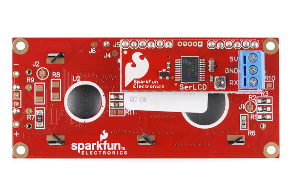
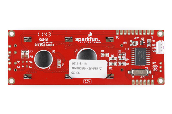
If the display is unreadable or washed out, the contrast may need to be adjusted. Send some text to the display (see the first example sketch above), then use a miniature Phillips screwdriver to gently turn the contrast trimpot labeled VR1 on the back of the display until the text is as clear as possible (please be gentle with the trimpot). This display also has a backlight that can be adjusted for best readability, see the LCD datasheet for information.
Bricked LCD
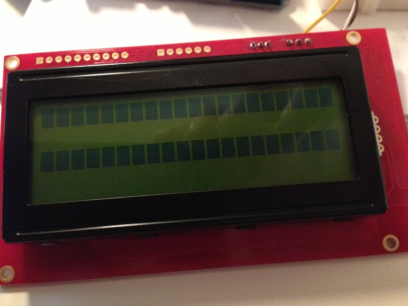
If you are seeing two rows of ASCII blocks (i.e. █ ) or random characters, it's possible that you might have bricked the serial enabled LCD by putting it into an unknown state. This is a common problem if you are uploading code to the Arduino while another device is connected to the same hardware UART line (i.e. pin 0 and 1). Some systems like Arduino send bootloader information out the serial port when the system starts up. This will cause the LCD to output random characters usually on the screen or not even show anything on the screen. If this is a problem, make sure to use a software defined serial pin to create a TX pin that doesn't get used during startup.
 |
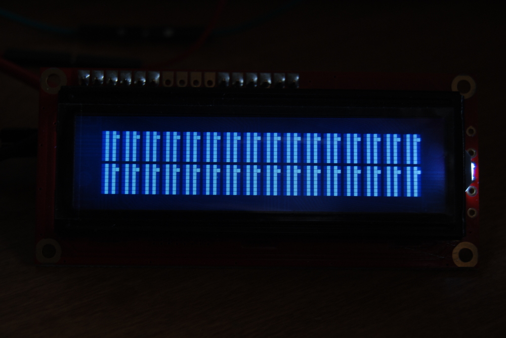 |
| Bricked Serial Enabled LCD 20x4 | Bricked Serial Enabled LCD 16x2 |
Recovering from Unknown State: Software Reset
If the Serial LCD gets into an unknown state and you are not able to communicate with it anymore, just write 0x12 in the loop so that it is constantly sending the hex value to the screen when the LCD's splash screen is active (or when the LCD is powered) to reset the unit back to 9600 baud as explained earlier. The screen will temporarily revert to 9600 baud until power is cycled. This is to allow you to regain control of the display if you set it to an unknown baud rate. Make sure to also change the baud rate in the EEPROM.
The old datasheet in section 3.4 indicates that you need to send a command character 0x7C in hexadecimal. If you look at the ASCII table for the non-printing control characters (CTRL-K through CTRL-P), there are hex values for the different baud rates that you would need to send to the LCD.
| Non-Printing Control Characters | Command Character | Description |
|---|---|---|
| <control>K | 0x0B [ 0d11 ] | Set to 2400 Baud |
| <control>L | 0x0C [ 0d12 ] | Set 4800 Baud |
| <control>M | 0x0D [ 0d13 ] | Set 9600 Baud (Default) |
| <control>N | 0x0E [ 0d14 ] | Set 14400 Baud |
| <control>O | 0x0F [ 0d15 ] | Set 19200 Baud |
| <control>P | 0x10 [ 0d16 ] | Set 38400 Baud |
| <control>R | 0x12 [ 0d18 ] | Reset to Default Baud While LCD's Splash Screen is Still Active |
All you have to do is create a new void function similar to the one below and call it when you are running the Arduino sketch file like this:
language:c
void changeBaud(){
  LCD.write(0x7C);// special command byte
  LCD.write(0x0D); //change current baud to 9600 baud
}
Here's some code with Arduino to try and unbrick the PIC16F88 on the serial enabled LCDs. This sometimes works and there is a higher probability of recovering your LCD if you still are able to see the splash screen.
Recovering from Unknown State: PICkit Programmer
The last resort is to use the PICkit 3 programmer and reupload the firmware on the LCD using MPLAB. If you are trying to recover a bricked serLCD backpack, you will need a few of the following materials listed below to connect to the programming header. The built-in serial enabled LCD will have standard 0.1" spaced headers so the IC hooks will not be necessary as long as there is contact with the pins during programming.

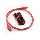
MPLAB PICkit 3
PGM-09973Using MPLAB X IDE v2.30
For this example, we will be using MPLAB X IDE V2.30 for Windows. Head over to MicroChip's archived downloads to download and install.
Also, make sure to download the hex file specific for your LCD to recover. We will be using the .hex file linked for the serial enabled LCD backpack below. If you are using the ones with the built-in serial, you will need to unzip the folder before using the file.
 |
 |
 |
| Download serlcd-v2_6_2line_10MHz (HEX) |
Download serlcd-v2_7_2line_10MHz (ZIP) |
Download serlcd-v2_7_4line_10MHz (ZIP) |
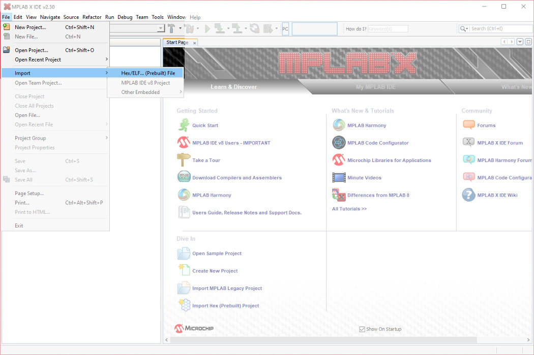
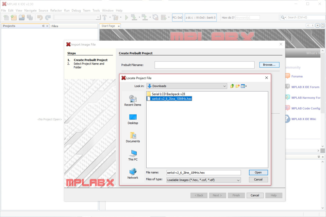
Once installed, select File > Import > Hex/ELF... (Prebuilt) File.
Click on the Browse... button and head to the location where the .hex file is stored on your computer. This will probably be in your recent downloads. Select the file and click on the Open button. This will automatically provide the path for the Prebuilt Filename which is .../serlcd-v2_6_2line_10MHz.hex.
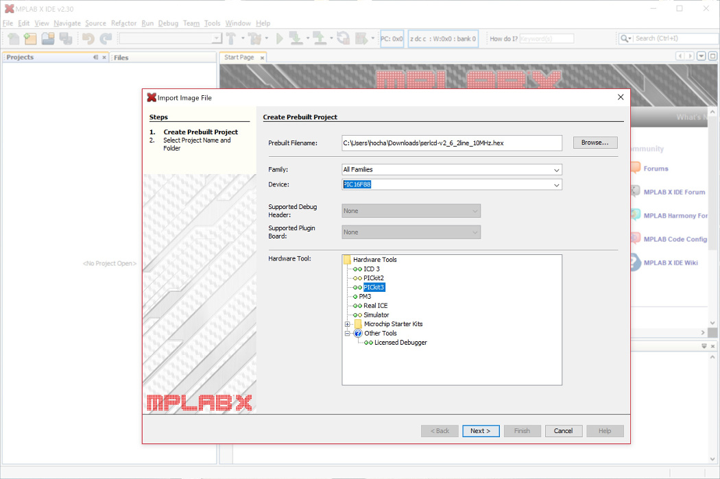
Then type in the Device field: PIC16F88. If you have a PIC16LF88 that is populated on the SerLCD backpack, this is the same device that you would select. The programmer will not notice a difference between the two PICs. Once selected, click on the Next > button.
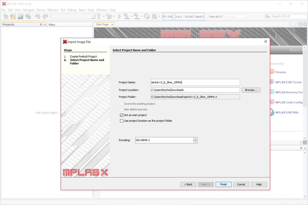
Click Finish to save as a project.
Connect the PICkit 3 to your computer using the USB cable. At this point, make the connection from the PICkit 3 to the programming pins of the LCD. Power the target (your PIC16LF88) from a separate power supply like an Arduino using wires. The PICkit 3 may not have enough power to power the target.
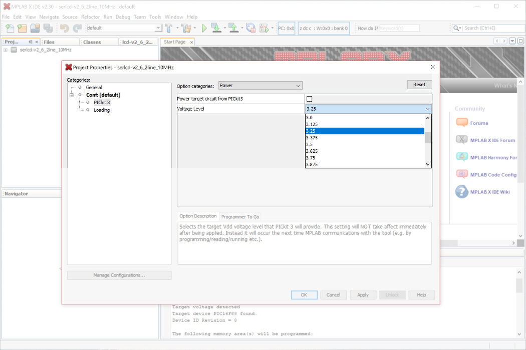
If you are using a 3.3V LCD, make sure to read the note highlighted in red below.
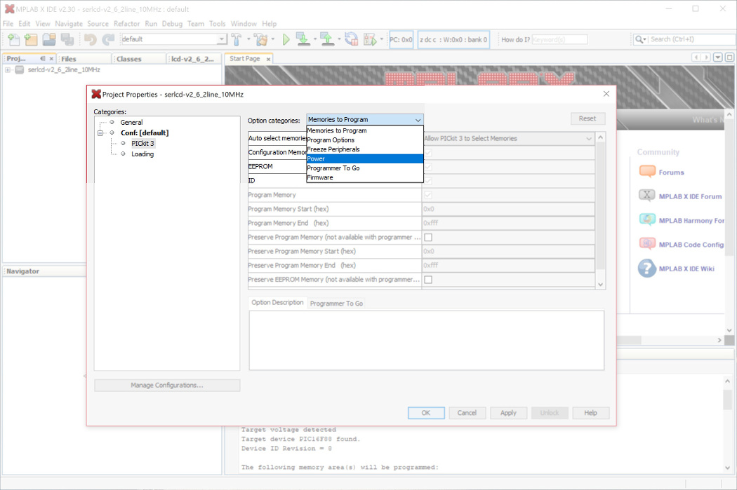
From the Categories: tree, select the PICkit 3 programmer. Under the Option categories: drop down menu, select Power.
Under Voltage Level, select 3.25. This should be a sufficient enough for flashing the PIC. Click OK button to save.
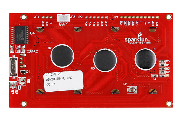
The PICkit 3 programmer's pinout is listed on page 15 of PICkit 3 user manual. To connect, start by connecting the LCD's programming header indicated by the polarity marker and move toward the other side.
| PICkit 3 Programmer Connector Pinout | Notes |
|---|---|
| VPP | Indicated by an Arrow, connect to pin "1" or a straight bar " ¯ " |
| VDD Target | 3.3V or 5V depending on your LCD |
| VSS (GND) | Ground |
| PGD | Data |
| PGC | Clock |
| LVP | Not Connected on SerLCD backpack |
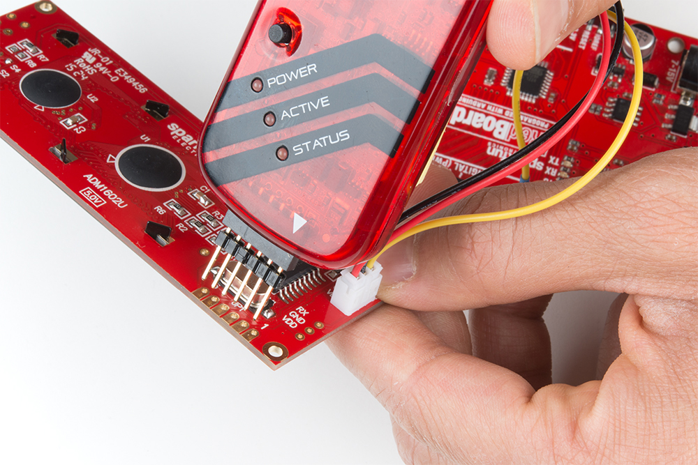
If you are using a 5V LCD, you can connect to the backpack with jumper wires (specifically wires with small pins) like the images shown below. When reflashing, the target voltage and GND pins were connected to the screw terminal. The PIC16LF88 can be reflashed as long as the pins are held in place during programming. Make sure the pins are not touching the LCD underneath.
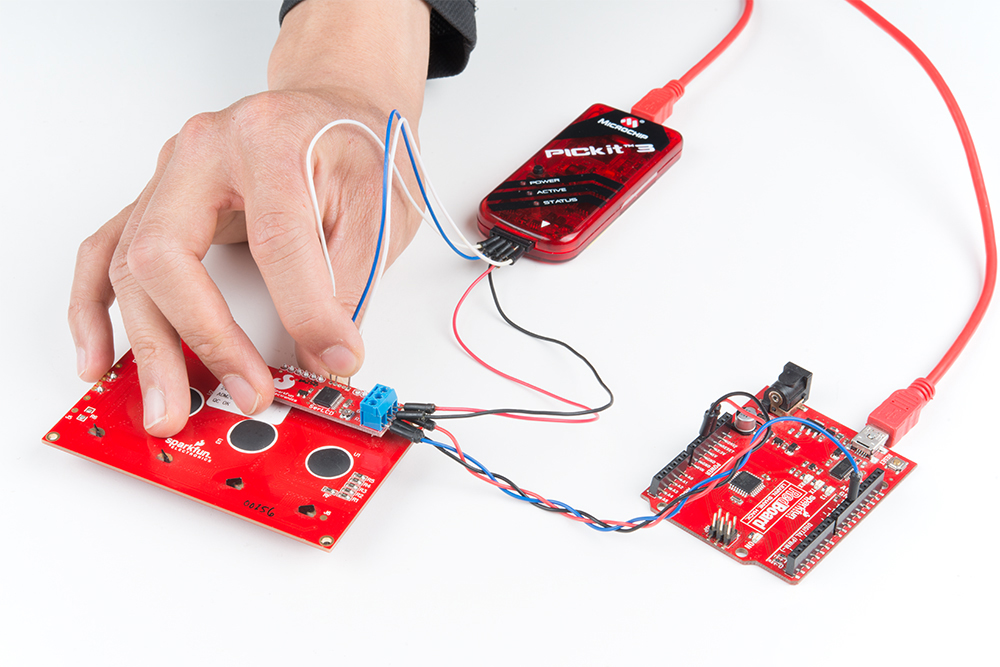 |
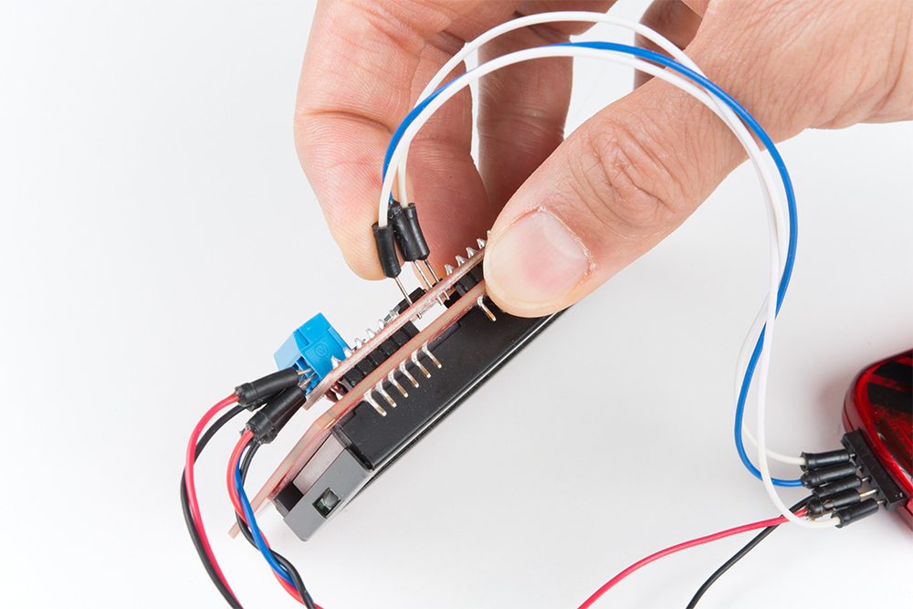 |
| Jumper Wires Between PICkit3 and SerLCD Backpack | Make Sure the Pins are Not Touching the LCD Underneath |
For those with the built-in serial enabled LCD programming pins, you could just connect using header pins by aligning the arrow to the pin "1".
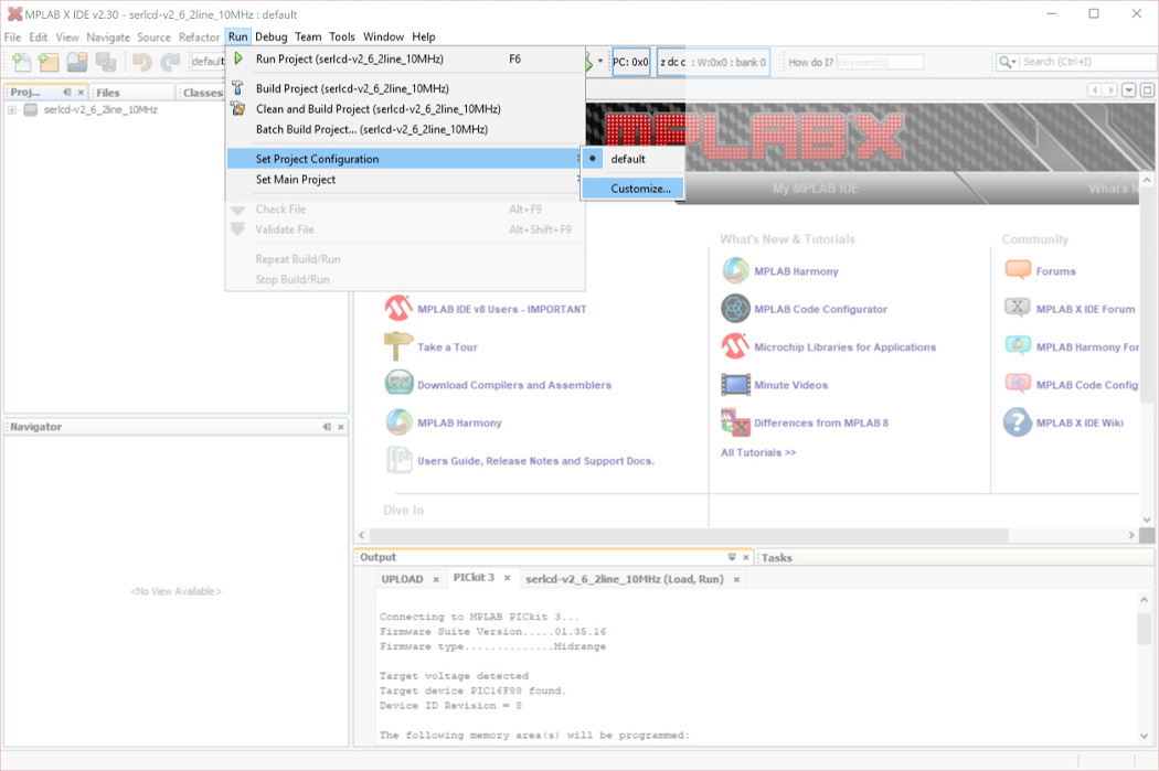
Then click on the icon's drop down menu that looks like the software is downloading to a PIC chip (i.e. the button next to the Run Project button) and select Make and Program Device Programmer to Go PICkit3 (Project serlcd-v2_6_2line_10MHz).
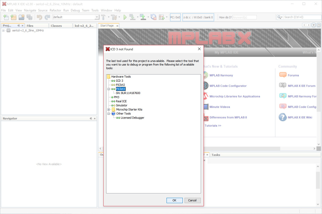
A message will pop up if you did not select the correct programmer.
Select PICkit 3 in the tree and click the OK button.
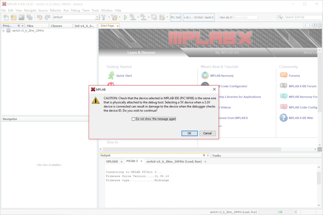
The software will pop up with this message:
If you followed the steps earlier to configure the PICkit 3 for a 3.3V LCD or are using a 5V LCD, click OK.
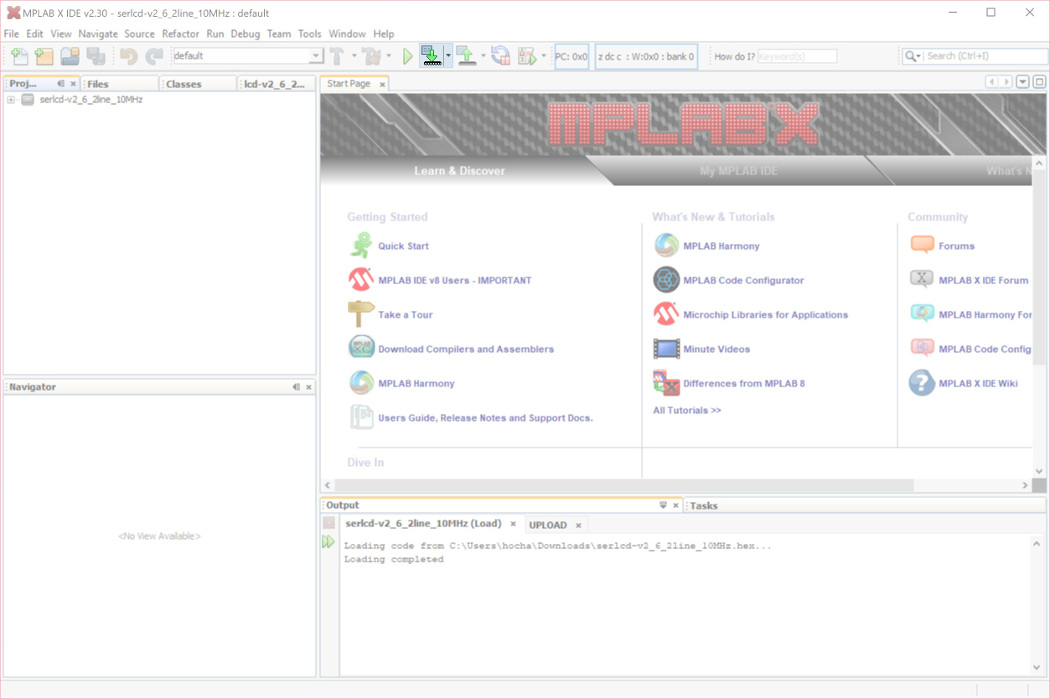
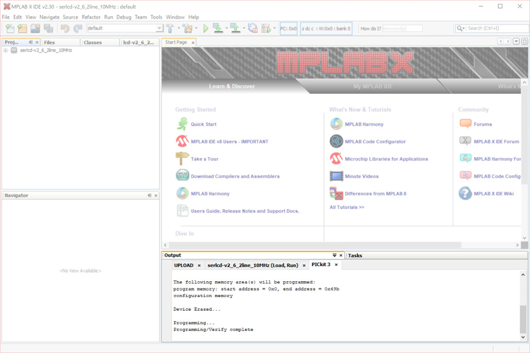
From there, the hex file should begin flashing on the chip and the program will run immediately after displaying this output:
language:c
*****************************************************

Connecting to MPLAB PICkit 3...
Firmware Suite Version.....01.28.90 *
Firmware type..............Midrange

Target voltage detected
Target device PIC16F88 found.
Device ID Revision = 8

The following memory area(s) will be programmed:
program memory: start address = 0x0, end address = 0x4ab
configuration memory

Device Erased...

Programming...
Programming/Verify complete
You should see this output at the bottom of the MPLAB X IDE.
Power cycle the screen. Congrats! We have recovered the LCD! Or, at least for a 16x2 character LCD... The firmware we flashed was set for the 16 characters and 2 lines. The next step is to configure the PIC for a 20x4 character LCD. To do this, we just need to send the control and command flags to adjust the width and lines. Place this your Arduino's setup() function after setting your Arduino's software serial port.
language:c
void set_20x4(){//set character LCD as 20x4
  LCD.write(0x7C); //command flag
  LCD.write(0x03);     //20 char wide
  LCD.write(0x7C); //command flag
  LCD.write(0x05);     //4 lines
  /*NOTE: Make sure to power cycle the serial enabled LCD
  after re-configuring the # char and lines.*/
}
Power cycle the screen and run the demo example to see if everything is working as expected. Ok, now we have recovered your 20x4 serial enabled LCD!
More Examples of Setting Cursor Position
As stated earlier, to set the LCD's cursor position, you would send the command character/flag. Then send additional number related to the cursor's position on the LCD screen. This example goes over how to set the cursor position for a 20x4 serial enabled LCD. Just add 128 to the cursor's position as stated on page 3 of the datasheet to place the cursor at the correct coordinates.
For example, if you are trying to place the cursor at (line 3, position 0), you would send the command character 0xFE and the associated coordinates. Looking at the datasheet, for the 20x4 serial enabled LCD screen, it looks like 128+20 = 148 . Therefore:
language:c
selectLineThree(){
    LCD.write(0xFE); //command flag
    LCD.write(148); //line 3 , position 0
}
As another example, if you are trying to place the cursor at (line 4, position 0), you would send the command character 0xFE and the associated coordinates. Looking at the datasheet, for the 20x4 serial enabled LCD screen, it looks like 128+84= 212. Therefore:
language:c
selectLineFour(){
    LCD.write(0xFE); //command flag
    LCD.write(212); //line 4 , position 0
}
Using the Serial Enabled LCD on an Atmega32U4's Hardware UART
If you are using the serial enabled LCD with an Atmega32U4-based Arduino (like a Pro Micro, Arduino Leonardo, Arduino LilyPad USB etc), you might need to add a small delay in the setup before you can get it working with the hardware UART (pins 0 and 1). Here's an example:
language:c
///test example using ATmega32U4's hardware UART and delay
void setup() {
  delay(2000);//add delay so the ATmega32U4 can have a second before sending serial data to the LCD
  Serial1.begin(9600);//set up the hardware UART baud
}

void loop() {
  Serial1.print("print something");//send something to the serial enabled LCD
  delay(50);
}
Software Serial for Arduino Due
Unfortunately, you are not able to use the serial enabled LCDs with an Arduino Due due the differences in how change interrupts are used for the ARM processor. The software serial library is not included in the Arduino Due's tree:
Try using the other hardware serial UARTs that are not connected to the Arduino Due's programming pins for uploading. Make sure to adjust the code for the hardware serial UARt.
Changing Width and Character Lines
To adjust the default width and character lines, there is some code listed in this example based on the datasheet to configure the serial enabled LCD.