Photon OLED Shield Hookup Guide
 b_e_n
b_e_n 
OLED Shield Overview
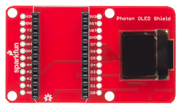
Pin Descriptions
Since the shield does all of the work for you, there's no need to actually wire these connections - but in case you're looking at datasheets, or code for the Microview or OLED breakout, this table will give you a clue as to what the shield is doing. As always, you can check the schematic for more info.
| OLED Shield Pin | Photon Pin | SPI Function | I2C Function | Notes |
|---|---|---|---|---|
| GND | GND | Ground | Ground | 0V |
| 3V3 (VDD) | 3V3 | Power | Power | Should be a regulated 3.3V supply. |
| D1 (SDI/MOSI) | A5 | MOSI | SDA | Serial data in |
| D0 (SCK) | A3 | SCK | SCL | SPI and I2C clock |
| D2 (SDO) | MISO | — | Can be unused in SPI mode. No function for I2C. | — |
| D/C | D6 | Data / Command | I2C address selection | Digital pin to signal if incoming byte is a command or screen data. |
| RST | D7 | Reset | Reset | Active-low screen reset. |
| CS | A2 | — | SPI chip select (active-low) | — |
Setting the Jumpers
With the board flipped over, you'll notice there are six jumpers. The majority of these jumpers are used to switch between SPI and I2C mode. As the board ships, these jumpers are set to configure the display in SPI mode.
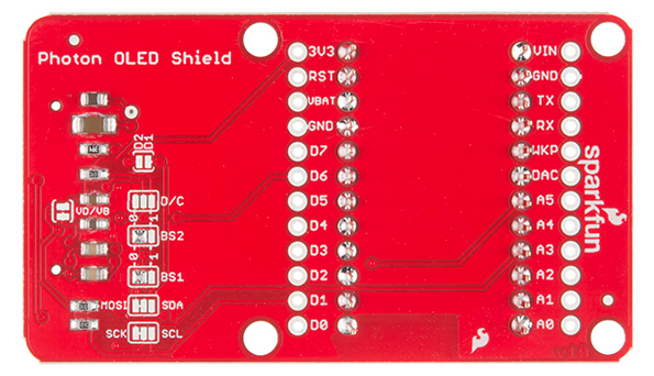
Here's an overview of each jumper, moving from left-to-right, top-to-bottom in the picture above:
- VD/VB -- This jumper shorts the digital power supply (VDD) to the battery power supply (VBAT). Because both of these supplies can be powered at 3.3V, an easy one-supply solution is to short them together and provide them a single supply. If you need to power the digital supply at something lower, like 1.8V, you may need to cut this jumper and provide two supplies.
- D1/D2 -- This jumper can be used to short D1 to D2. If you want to use SPI, leave this jumper open. If you're using I2C, short the jumper. By default this jumper is open.
- D/C -- This jumper can be used to short D/C to either 3.3V (1) or 0V (0). In I2C mode, the D/C pin sets the 7-bit address of the display. In SPI mode this jumper should be left open, as the D/C pin needs to be toggled to determine if an incoming byte is data or command.
- BS2 and BS1 -- These pins on the OLED determine which interface you're using to control the OLED. With the two signals, there are four possible combinations:
BS2 BS1 Interface 0 0 SPI 0 1 I2C 1 0 8-bit Parallel (6800) 1 1 8-bit Parallel (8080)
That brief overview should cover the 99% use case. Consult the schematic and the notes therein if you have any questions about jumpers or pins.