OBD II UART Hookup Guide
 Toni_K
First Communcation
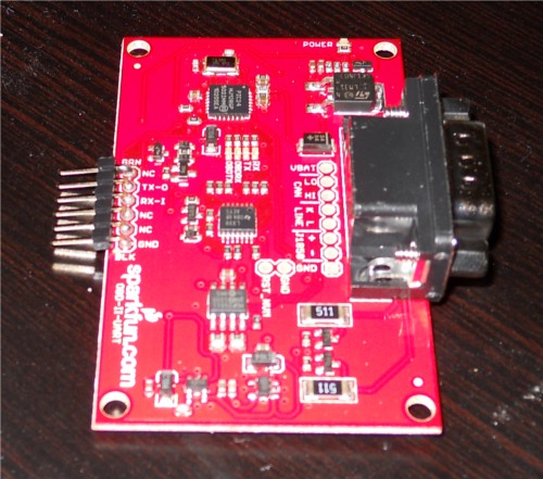
Soldering Headers
To create a solid electrical connection with any other components (such as an Arduino or an FTDI Basic), you need to solder headers to the board. For use with the FTDI Basic, it is easiest to solder male headers into the 6-pin header row at the edge of the board. Once you have this done, your board should look similar to this.
Connecting to a Vehicle OBD Port
You will need to connect the OBD-II board to the OBD port on your vehicle. Depending on the make and model of your car, the port location may vary. Consult your owner's maunal if you cannot locate the port.
Once you have located your OBD port, you will need to hook up the OBD-to-DB9 cable to the vehicle's port.
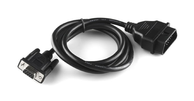
The mating end of the cable tends to be a very tight fit and require a bit of force to get it sitting securely, so it's usually easier to start hooking everything together between the car and the cable. Once you get the car and the cable connected, then connect the DB9 end of the cable to the OBD-II board.
Connecting over a Serial Port
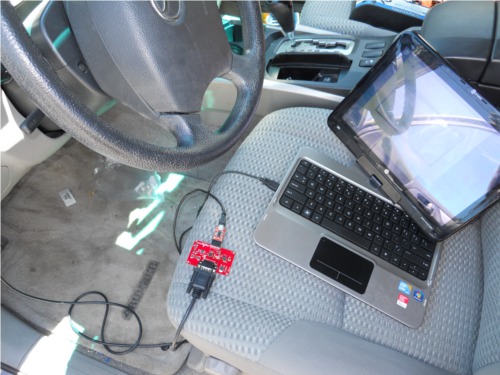
Once you have your headers attached to your board, and you've connected to your vehicle using the OBD-DB9 cable, you can start communicating withe OBD-II board over through a serial port using an FTDI Basic breakout board. The FTDI pinout matches with the 6 pin header on the OBD-II board, but only connects TX, RX and GND. Connect the FTDI board to the computer via a mini-USB cable, and open up a serial terminal on your computer. Configure the serial connection to 9600 bps, 8 data bits, 1 stop bit and no parity.
Once you have your serial terminal set up, you will communicate with the OBD-II board by using AT commands. These commands always start with "AT". The OBD-II board is case-insensitive, so don't stress about only using capital letters. After sending "AT", the next letters sent to the board will be the commands that should be executed by the board. You can find a list of all of the available AT commands here.
To start communicating with the board, type "ATZ" into your terminal window and hit "enter". This will send the command to reset the board. You should see some LEDs flash on your board and then see the start-up prompt in the terminal window.
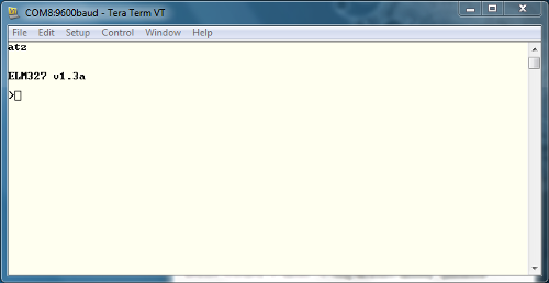
If you receive back any garbled characters, double check that you have the correct serial port settings in your terminal.
Once you have proper communcation with your board set up, try reading the OBD-II UART system voltage. Type "ATRV" into the terminal window and hit enter. The board should then return the system voltage to you.
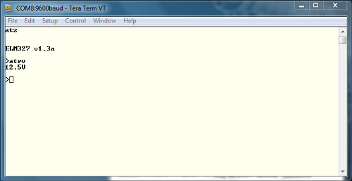
This voltage reading should match your vehicle's battery voltage.
To read additional OBD parapters for the vehicle, the OBD-II board must first be configured to the correct OBD protocol. There are several different OBD protocols, so it can be confusing attempting to find the correct one. However, like all things awesome, this OBD-II board automatically detects the protocol. To use this auto-detect feature, the vehicle's ignition must be in the 'On' position. The vehicle doesn't necessarily need to be running however. Once the ignition is on, send the command "ATSP0" (that's a trailing zero). The board will then reply with "OK" once the proper protocol has been detected.
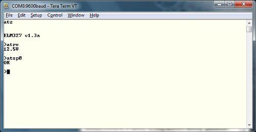
Once you have the proper protocol detected on your board, you can start sending OBD commands to the board.