nRF24L01+ Transceiver Hookup Guide
 Toni_K
 Hardware Overview
Antenna Options
SparkFun carries two versions of the breakout, listed below.
On-Board Chip Antenna
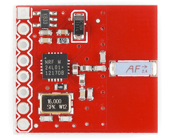
The first version is the SparkFun Transceiver Breakout - nRF24L01+ with chip antenna. The on-board chip antenna allows for a more compact version of the breakout. However, the smaller antenna also means a lower transmission range. Keep that in mind if you plan on mounting this board in an enclosure. The enclosure material may also decrease the range of this board, as you cannot move the antenna outside of any interference. This antenna should be suitable for most applications.
RP-SMA
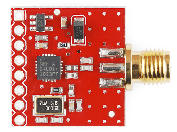
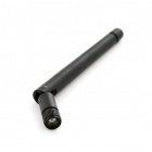
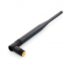
If you need more range in your wireless connection or if you need to move your antenna outside an interference zone, we recommend the RP-SMA antenna version of the breakout. You can learn more about SMA connectors here. This version works with the RP-SMA 2.4GHz antenna and its larger counterpart. Because of the external antenna on this version of the breakout, it has a greater range than the on-board antenna version.
Pins
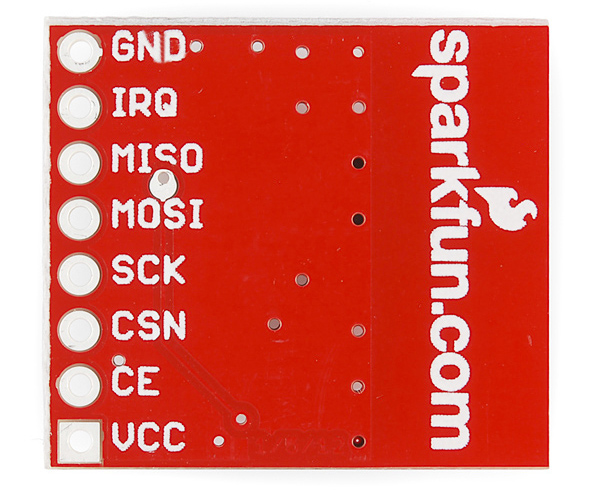
While the nRF24L01+ IC has 20 pins available, our breakout board simplifies this down to the 8 pins required to get up and running. These pins are the same on both versions of the board. The pins function as follows:
- GND - Ground
- IRQ - Interrupt pin. This pin is active
LOW. - MISO - 3.3V-5V tolerant SPI slave output.
- MOSI - 3.3V-5V tolerant SPI slave input.
- SCK - 3.3V-5V tolerant SPI clock.
- CSN - 3.3V-5V tolerant SPI chip select.
- CE - 3.3V-5V tolerant chip enable. This pin toggles the nRF24L01+ IC between transmit (TX), receive (RX), standby, and power-down mode.
- VCC - This is VRAW and is regulated on-board down to 3.3V for the proper functionality of the nRF24L01+. Voltage range on this pin is 3.3V-7V.
Functionality
Transmission Mode
The IC can either work in transmit or receive mode. This mode is determined by both the CE pin state, the PWR_UP register, and the PRIM_RX register. The following chart shows the various configurations.
| Mode | PWR_UP Register | PRIM_RX Register | CE Pin | FIFO State |
|---|---|---|---|---|
| RX Mode | 1 | 1 | 1 | - |
| TX Mode | 1 | 0 | 1 | Data in TX FIFOs. Will empty all levels in TX FIFOs |
| TX Mode | 1 | 0 | Minimum 10μs high pulse | Data in TX FIFOs.Will empty one level in TX FIFOs. |
| Standby-II | 1 | 0 | 1 | TX FIFO empty. |
| Standby-I | 1 | - | 0 | No ongoing packet transmission. |
| Power Down | 0 | - | - | - |