nRF24L01+ Transceiver Hookup Guide
Contributors:
 Toni_K
Toni_K Hardware Hookup
Solder Connection Points
We recommend soldering headers to the nRF24L01+ board to allow you to prototype your circuit. To avoid interference with the antenna on the nRF24L01+, use right-angle male headers.

If you need a review for PTH soldering, check out our solder tutorial.
How to Solder: Through-Hole Soldering
This tutorial covers everything you need to know about through-hole soldering.
Connect the Wires
Now that you have your headers attached, you can plug in the jumper wires. Connect the RedBoard and nRF24L01 as listed.
RedBoard → nRF24L01+
- 5V → VCC
- GND → GND
- D8 → IRQ
- D9 → CE
- D10 → CSN
- D11 → MOSI
- D12 → MISO
- D13 → SCK
Final Circuit
Once you have everything connected, your system should look like the following:
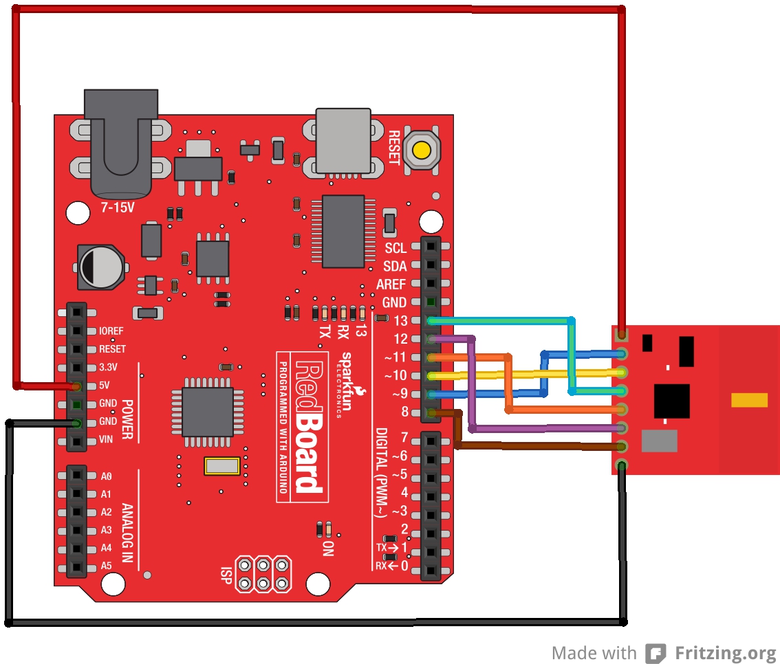
nRF24L01+ Circuit Assembly
Repeat!
Since these are radio modules, you'll need at least two modules to talk to each other. Duplicate the connections between another RedBoard and nRF24L01+ module. Don't forget to attach the antenna to your nRF24L01+ if you have the RP-SMA version.