nRF24L01+ Transceiver Hookup Guide
 Toni_K
 Introduction
These breakout boards provide SPI access to the nRF24L01+ transceiver module from Nordic Semiconductor. The transceiver operates at 2.4 GHz and with power supplies 3.3V-5V. It has 250kbps, 1Mbps and 2Mbps on-air data-rate options and is applicable for low-power applications. The breakout boards are available with an on-board antenna or an option to add an external antenna to the RP-SMA connector.
Required Materials
To follow along with this tutorial, we recommend you have access to the following materials. You may not need everything, depending on what you already have. Add it to your cart, read through the guide, and adjust the cart as necessary.
Suggested Reading
If you aren't familiar with the following concepts, we recommend reviewing them before beginning to work with the nRF24L01+ Breakouts.
How to Solder: Through-Hole Soldering
Serial Peripheral Interface (SPI)
How to Power a Project
Installing Arduino IDE
Hardware Overview
Antenna Options
SparkFun carries two versions of the breakout, listed below.
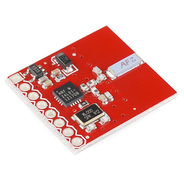
On-Board Chip Antenna
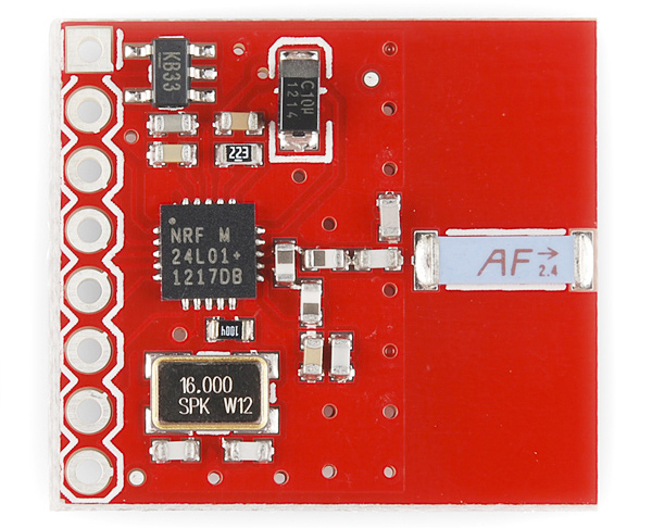
The first version is the SparkFun Transceiver Breakout - nRF24L01+ with chip antenna. The on-board chip antenna allows for a more compact version of the breakout. However, the smaller antenna also means a lower transmission range. Keep that in mind if you plan on mounting this board in an enclosure. The enclosure material may also decrease the range of this board, as you cannot move the antenna outside of any interference. This antenna should be suitable for most applications.
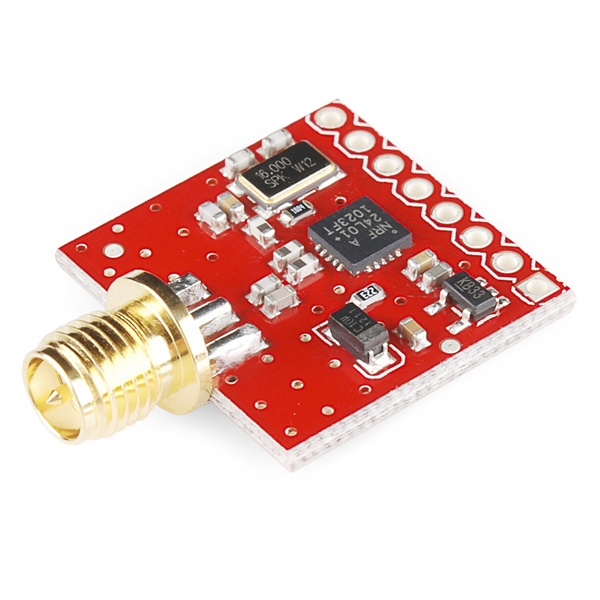
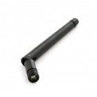
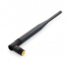
RP-SMA
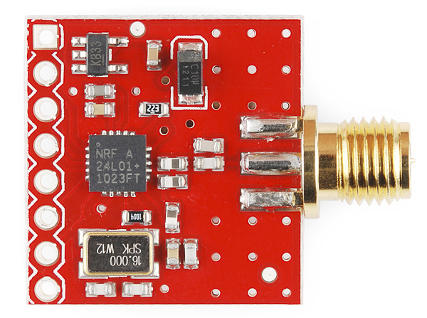
If you need more range in your wireless connection or if you need to move your antenna outside an interference zone, we recommend the RP-SMA antenna version of the breakout. You can learn more about SMA connectors here. This version works with the RP-SMA 2.4GHz antenna and its larger counterpart. Because of the external antenna on this version of the breakout, it has a greater range than the on-board antenna version.
Pins
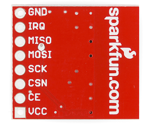
While the nRF24L01+ IC has 20 pins available, our breakout board simplifies this down to the 8 pins required to get up and running. These pins are the same on both versions of the board. The pins function as follows:
- GND - Ground
- IRQ - Interrupt pin. This pin is active
LOW. - MISO - 3.3V-5V tolerant SPI slave output.
- MOSI - 3.3V-5V tolerant SPI slave input.
- SCK - 3.3V-5V tolerant SPI clock.
- CSN - 3.3V-5V tolerant SPI chip select.
- CE - 3.3V-5V tolerant chip enable. This pin toggles the nRF24L01+ IC between transmit (TX), receive (RX), standby, and power-down mode.
- VCC - This is VRAW and is regulated on-board down to 3.3V for the proper functionality of the nRF24L01+. Voltage range on this pin is 3.3V-7V.
Functionality
Transmission Mode
The IC can either work in transmit or receive mode. This mode is determined by both the CE pin state, the PWR_UP register, and the PRIM_RX register. The following chart shows the various configurations.
| Mode | PWR_UP Register | PRIM_RX Register | CE Pin | FIFO State |
|---|---|---|---|---|
| RX Mode | 1 | 1 | 1 | - |
| TX Mode | 1 | 0 | 1 | Data in TX FIFOs. Will empty all levels in TX FIFOs |
| TX Mode | 1 | 0 | Minimum 10μs high pulse | Data in TX FIFOs.Will empty one level in TX FIFOs. |
| Standby-II | 1 | 0 | 1 | TX FIFO empty. |
| Standby-I | 1 | - | 0 | No ongoing packet transmission. |
| Power Down | 0 | - | - | - |
Hardware Hookup
Solder Connection Points
We recommend soldering headers to the nRF24L01+ board to allow you to prototype your circuit. To avoid interference with the antenna on the nRF24L01+, use right-angle male headers.

If you need a review for PTH soldering, check out our solder tutorial.
How to Solder: Through-Hole Soldering
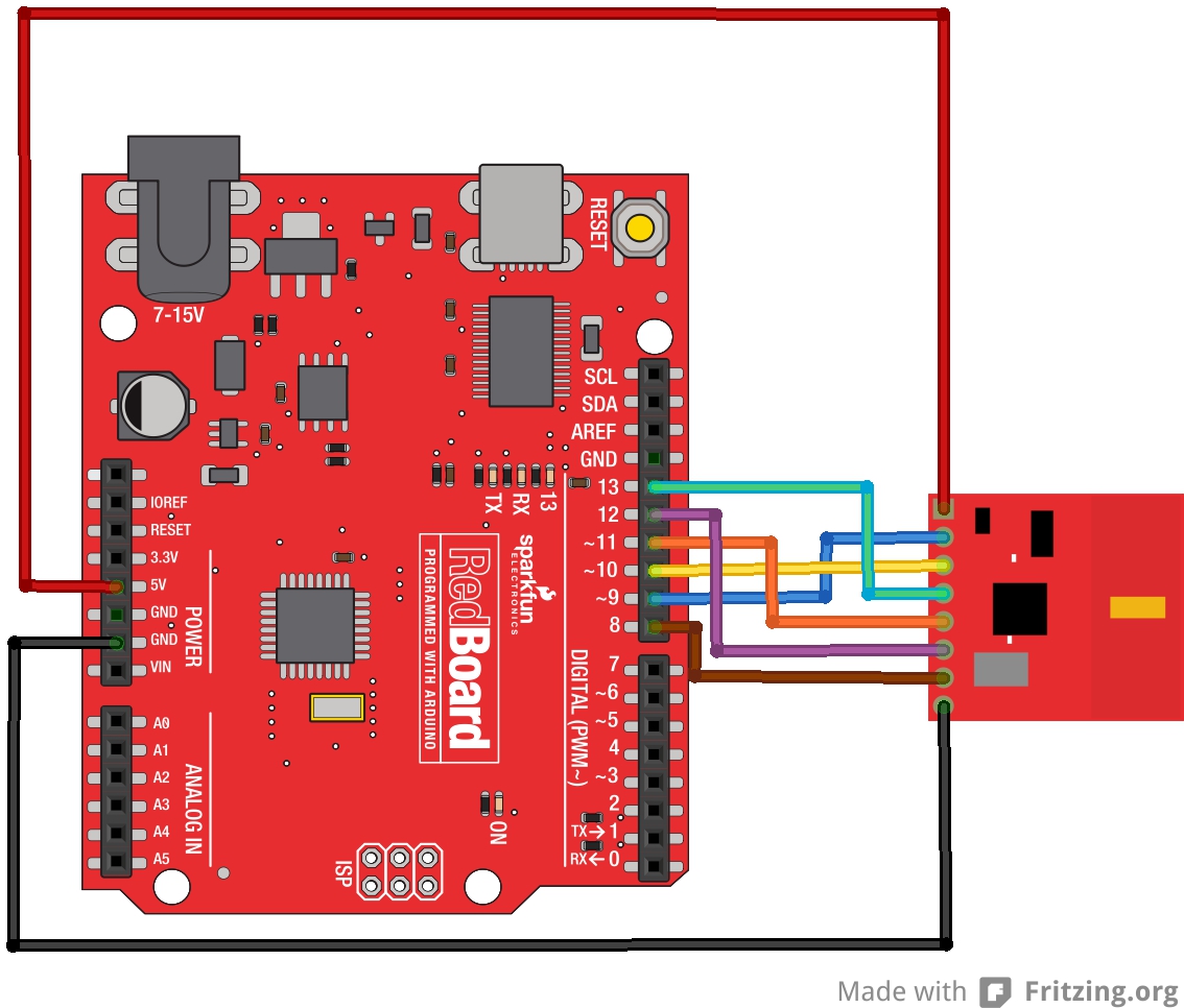
Connect the Wires
Now that you have your headers attached, you can plug in the jumper wires. Connect the RedBoard and nRF24L01 as listed.
RedBoard → nRF24L01+
- 5V → VCC
- GND → GND
- D8 → IRQ
- D9 → CE
- D10 → CSN
- D11 → MOSI
- D12 → MISO
- D13 → SCK
Final Circuit
Once you have everything connected, your system should look like the following:
Repeat!
Since these are radio modules, you'll need at least two modules to talk to each other. Duplicate the connections between another RedBoard and nRF24L01+ module. Don't forget to attach the antenna to your nRF24L01+ if you have the RP-SMA version.
Arduino Code
There are a lot of libraries available for this module, but we recommend using the RF24 library, originally written by maniacBug, and updated for Arduino 1.6x by TMRh20.
You can find the most up-to-date version of the library here. Alternatively, you can download this zip and install it into your Arduino IDE libraries folder. If you need help with the library installation, please check out our tutorial.
Once you have your code properly installed, open up Examples → RF24 → GettingStarted.ino.
Check out the User Configuration section of the code, and make sure you update yours as shown below.
language:c
/****************** User Config ***************************/
/***      Set this radio as radio number 0 or 1         ***/
bool radioNumber = 1;

/* Hardware configuration: Set up nRF24L01 radio on SPI bus plus pins 9 & 10 */
RF24 radio(9,10);
One radio should have the radioNumber set to 0 and the other should be set to 1.
Upload the code to your Redboards. Once you have them both set up, you can open up two terminals set at 115200 bps, 8-N-1, and you should see the following appear on the terminal.
language:c
RF24/examples/GettingStarted
*** PRESS 'T' to begin transmitting to the other node
Press T in one terminal, press R in the other, and wait until you start seeing your radios communicating! You should see something similar in your terminal.

Resources and Going Further
Now that you have your nRF24L01+ up and running, you can start creating your own awesome wireless projects. There are several other examples in the library -- use these to to keep exploring your nRF24L01+ modules or modify them for your own personal projects.
For more on the nRF24L01+, check out the links below:
Need some inspiration for your next project? Check out some of these related tutorials:
Heartbeat Straight Jacket
Or the following links for more examples with other development boards:
For more wireless fun, check out these other SparkFun tutorials:
Blynk Board Project Guide
Using Artnet DMX and the ESP32 to Drive Pixels
Getting Started with the Autonomous Kit for the Sphero RVR
ARGOS (ARTIC R2) Satellite Communication Guide
Have a great project done? Let us know - we'd love to see it! If you have any feedback, please visit the comments or contact our technical support team at TechSupport@sparkfun.com.