Multiplexer Breakout Hookup Guide
 jimblom
Arduino Example: Output
Now that you've got a handle on how to use the Multiplexer works and have the board assembled, here are a few quick example Arduino sketches to help demonstrate both output and input capabilities of the chip.
The Circuit
To get the most out of this example, you'll need to connect some sort of output device to each of the independent I/O pins (Y0-Y7). For example, grab a pack of LEDs and some 330Ω resistors for a quick hardware-verifying circuit.
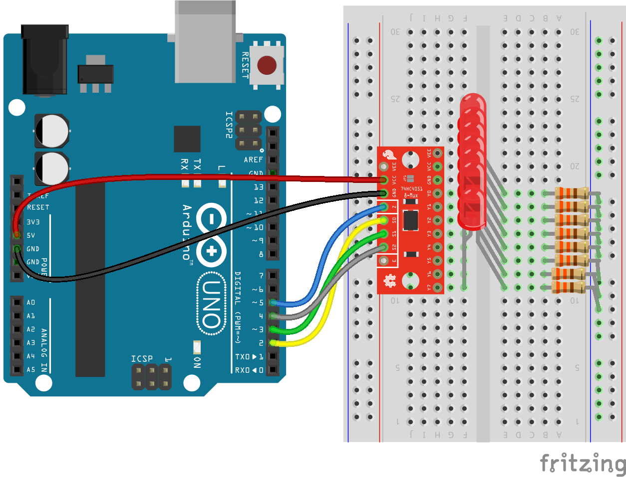
In this example, S0, S1, and S2 are connected to Arduino pins 2, 3 and 4 respectively. "Z" is connected to pin 5, which the example uses to produce PWM "analog output" signals.
VCC is connected to the Arduino 5V pin, and GND goes to GND. The breakout board's JP1 is left intact, shorting VEE to GND.
Finally, the Y0-Y7 pins are all connected to LED/resistor pairs, with the positive anode end of the LED connected to the Y-pin and the resistor connecting the LED's cathode to ground. This way, when the output is selected and "Z" goes high, the LED on that output will turn on.
The Sketch
Here's the code for the above circuit. Upload it, and enjoy the cycling, breathing LEDs!
Note: This example assumes you are using the latest version of the Arduino IDE on your desktop. If this is your first time using Arduino, please review our tutorial on installing the Arduino IDE.
If you have not previously installed an Arduino library, please check out our installation guide.language:c
/******************************************************************************
Mux_Analog_Output
SparkFun Multiplexer Output Example
Jim Lindblom @ SparkFun Electronics
August 15, 2016
https://github.com/sparkfun/74HC4051_8-Channel_Mux_Breakout
This sketch demonstrates how to use the SparkFun Multiplexer
Breakout - 8 Channel (74HC4051) to drive eight outputs using
four digital pins.
Hardware Hookup:
Mux Breakout ----------- Arduino
S0 ------------------- 2
S1 ------------------- 3
S2 ------------------- 4
Z -------------------- 5
VCC ------------------- 5V
GND ------------------- GND
(VEE should be connected to GND)
Development environment specifics:
Arduino 1.6.9
SparkFun Multiplexer Breakout - 8-Channel(74HC4051) v10
(https://www.sparkfun.com/products/13906)
******************************************************************************/
/////////////////////
// Pin Definitions //
/////////////////////
const int selectPins[3] = {2, 3, 4}; // S0~2, S1~3, S2~4
const int zOutput = 5; // Connect common (Z) to 5 (PWM-capable)
const int LED_ON_TIME = 500; // Each LED is on 0.5s
const int DELAY_TIME = ((float)LED_ON_TIME/512.0)*1000;
void setup()
{
// Set up the select pins, as outputs
for (int i=0; i<3; i++)
{
pinMode(selectPins[i], OUTPUT);
digitalWrite(selectPins[i], LOW);
}
pinMode(zOutput, OUTPUT); // Set up Z as an output
}
void loop()
{
// Cycle from pins Y0 to Y7 first
for (int pin=0; pin<=7; pin++)
{
// Set the S0, S1, and S2 pins to select our active
// output (Y0-Y7):
selectMuxPin(pin);
// While the output is selected ramp the LED intensity up
for (int intensity=0; intensity<=255; intensity++)
{
analogWrite(zOutput, intensity);
delayMicroseconds(DELAY_TIME);
}
// Then bring the analog output value down:
for (int intensity=255; intensity>=0; intensity--)
{
analogWrite(zOutput, intensity);
delayMicroseconds(DELAY_TIME);
}
}
// Now cycle from pins Y6 to Y1
for (int pin=6; pin>=1; pin--)
{
selectMuxPin(pin); // Select the pin
// Cycle the intensity up:
for (int intensity=0; intensity<=255; intensity++)
{
analogWrite(zOutput, intensity);
delayMicroseconds(DELAY_TIME);
}
// Then ramp the output down:
for (int intensity=255; intensity>=0; intensity--)
{
analogWrite(zOutput, intensity);
delayMicroseconds(DELAY_TIME);
}
}
}
// The selectMuxPin function sets the S0, S1, and S2 pins
// accordingly, given a pin from 0-7.
void selectMuxPin(byte pin)
{
if (pin > 7) return; // Exit if pin is out of scope
for (int i=0; i<3; i++)
{
if (pin & (1<<i))
digitalWrite(selectPins[i], HIGH);
else
digitalWrite(selectPins[i], LOW);
}
}
The magic part of this code is the selectMuxPin(byte pin) function at the bottom.
language:c
const int selectPins[3] = {2, 3, 4}; // S-pins to Arduino pins: S0~2, S1~3, S2~4
...
// The selectMuxPin function sets the S0, S1, and S2 pins to select the give pin
void selectMuxPin(byte pin)
{
  if (pin > 7) return; // Exit if pin is out of scope
  for (int i=0; i<3; i++)
  {
    if (pin & (1<<i))
      digitalWrite(selectPins[i], HIGH);
    else
      digitalWrite(selectPins[i], LOW);
  }
}
Given a pin number between 0 and 7, selectMuxPin configures the S0-S2 pins to connect that Y-pin to Z. If you take nothing else from this example, that function may prove the most handy in your future multiplexing endeavors.