Multiplexer Breakout Hookup Guide
 jimblom
Arduino Example: Input
In this example, we'll switch gears and test out the 74HC4051's analog signal support. By connecting "Z" to an analog input on the Arduino, we can turn one ADC pin into eight!
The Circuit
You can leave the select pins (S0-S2) tied to Arduino pins 2, 3, and 4, but re-route the Z jumper wire to A0. As for the Y-pins, you can connect potentiometers, photocells, or create voltage dividers on all eight inputs.
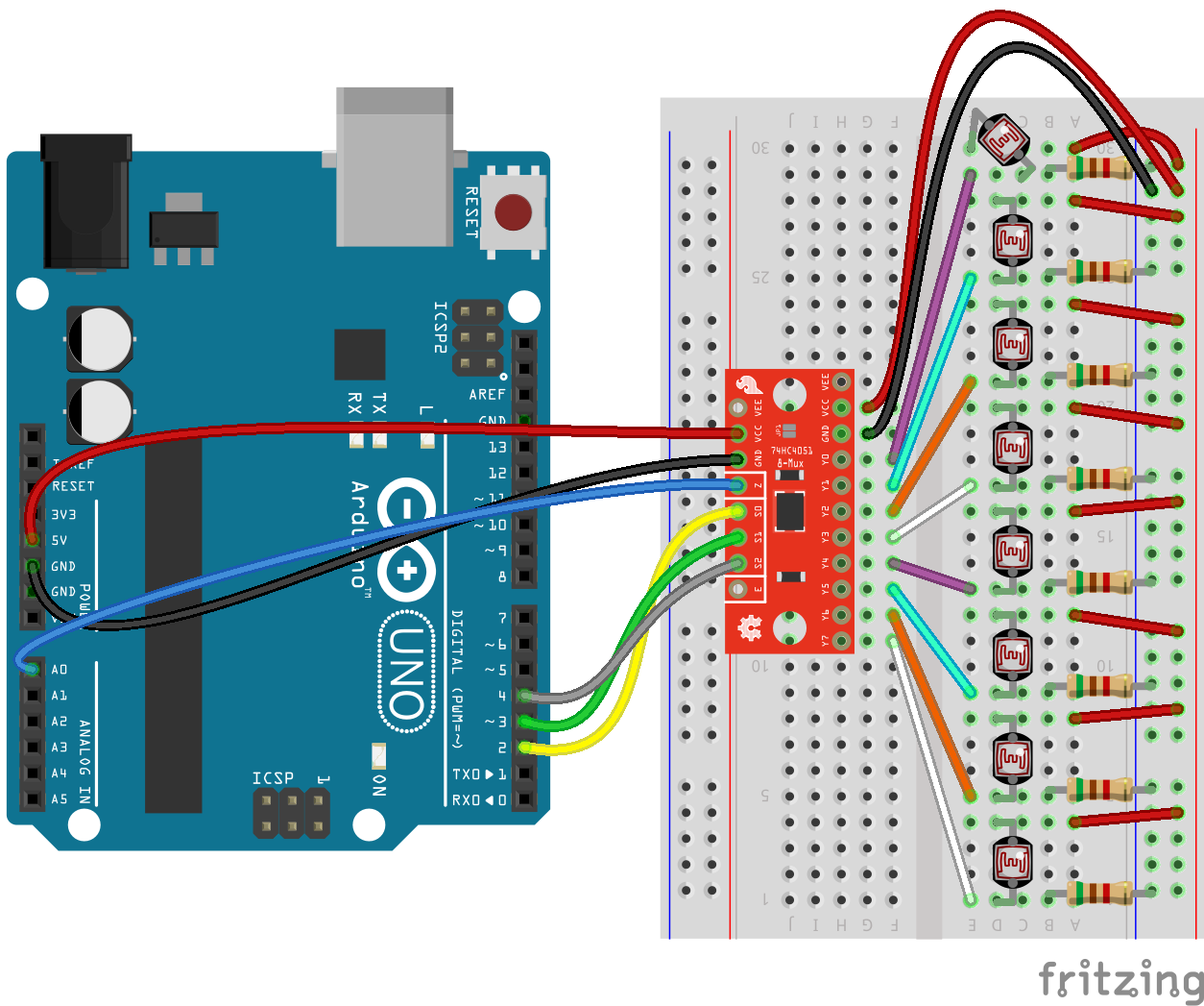
In lieu of a collection of eight analog input devices, you can just use jumper wires to short the input pins to either VCC or GND. That way you can at least prove to yourself that it works.
The Sketch
Here's the sketch for the above circuit:
language:c
/******************************************************************************
Mux_Analog_Input
SparkFun Multiplexer Analog Input Example
Jim Lindblom @ SparkFun Electronics
August 15, 2016
https://github.com/sparkfun/74HC4051_8-Channel_Mux_Breakout

This sketch demonstrates how to use the SparkFun Multiplexer
Breakout - 8 Channel (74HC4051) to read eight, separate
analog inputs, using just a single ADC channel.

Hardware Hookup:
Mux Breakout ----------- Arduino
     S0 ------------------- 2
     S1 ------------------- 3
     S2 ------------------- 4
     Z -------------------- A0
    VCC ------------------- 5V
    GND ------------------- GND
    (VEE should be connected to GND)

The multiplexers independent I/O (Y0-Y7) can each be wired
up to a potentiometer or any other analog signal-producing
component.

Development environment specifics:
Arduino 1.6.9
SparkFun Multiplexer Breakout - 8-Channel(74HC4051) v10
(https://www.sparkfun.com/products/13906)
******************************************************************************/
/////////////////////
// Pin Definitions //
/////////////////////
const int selectPins[3] = {2, 3, 4}; // S0~2, S1~3, S2~4
const int zOutput = 5;
const int zInput = A0; // Connect common (Z) to A0 (analog input)

void setup()
{
  Serial.begin(9600); // Initialize the serial port
  // Set up the select pins as outputs:
  for (int i=0; i<3; i++)
  {
    pinMode(selectPins[i], OUTPUT);
    digitalWrite(selectPins[i], HIGH);
  }
  pinMode(zInput, INPUT); // Set up Z as an input

  // Print the header:
  Serial.println("Y0\tY1\tY2\tY3\tY4\tY5\tY6\tY7");
  Serial.println("---\t---\t---\t---\t---\t---\t---\t---");
}

void loop()
{
  // Loop through all eight pins.
  for (byte pin=0; pin<=7; pin++)
  {
    selectMuxPin(pin); // Select one at a time
    int inputValue = analogRead(zInput); // and read Z
    Serial.print(String(inputValue) + "\t");
  }
  Serial.println();
  delay(1000);
}

// The selectMuxPin function sets the S0, S1, and S2 pins
// accordingly, given a pin from 0-7.
void selectMuxPin(byte pin)
{
  for (int i=0; i<3; i++)
  {
    if (pin & (1<<i))
      digitalWrite(selectPins[i], HIGH);
    else
      digitalWrite(selectPins[i], LOW);
  }
}
After uploading the sketch, open your serial monitor and set the baud rate to 9600. Here you'll see the analog values from all eight independent I/O (Y0-Y7) read and printed out once a second.
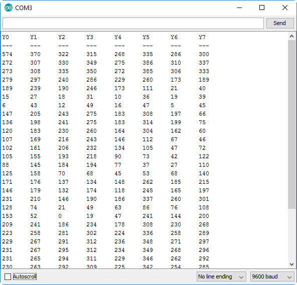
Toggle your inputs, or switch out some jumper wires to see the values change.
This example uses that same selectMuxPin function to set the S0, S1, and S2 pins. But instead of writing out to the Z pin, we read from it.