MLX90614 IR Thermometer Hookup Guide
 jimblom
MLX90614 Overview
Internally, the MLX90614 is a pairing of two devices: an infrared thermopile detector and a signal-conditioning application processor.
Per the Stefan-Boltzman law, any object that isn't below absolute zero (0°K) emits (non-human-eye-visible) light in the infrared spectrum that is directly proportional to its temperature. The special infrared thermopile inside the MLX90614 senses how much infrared energy is being emitted by materials in its field of view, and produces an electrical signal proportional to that.
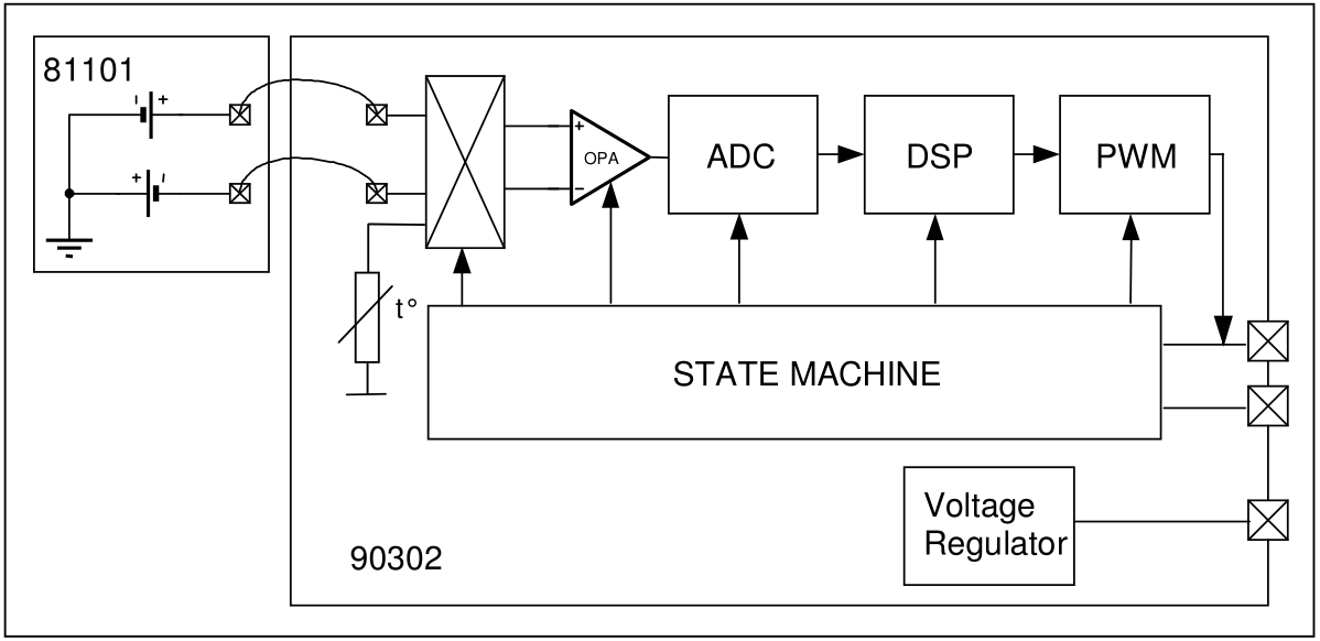
That voltage produced by the thermopile is picked up by the application processor's 17-bit ADC, then conditioned before being passed over to a microcontroller.
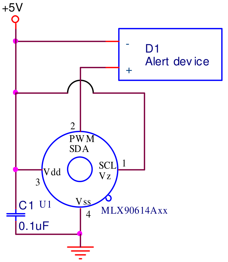
MLX90614 Pinout
The MLX90614 comes in a TO-39 "can" package with four legs: two for power, and two for the SMBus interface. A "notch" on the package helps to indicate which pin is which.

Capabilities
The MLX90614 produces two temperature measurements: an object and an ambient reading. The object temperature is the non-contact measurement you'd expect from the sensor, while the ambient temperature measures the temperature on the die of the sensor. The ambient can be useful to calibrate the data, but the real meat of our readings will come from the object temperature measurement.
The object temperature measurements can range from -70 to 382.2 °C (-94 to 719.96 °F), while the ambient temperature reading ranges from -40 to 125 °C.
Both the ambient temperature and object temperatures have a resolution of 0.02 °C.
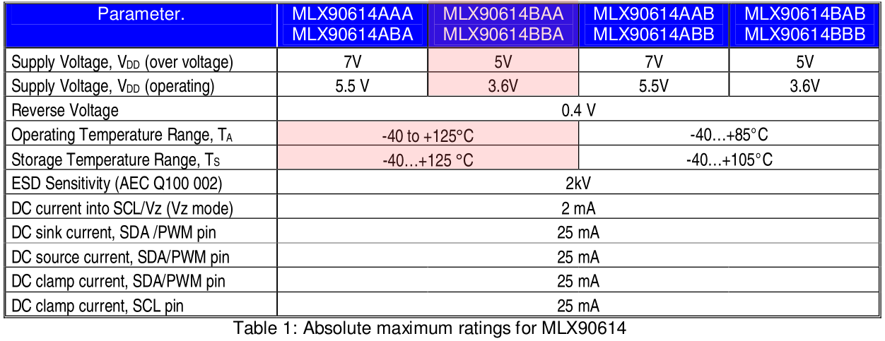
MLX90614BAA
There are many varieties of the MLX90614 out there, each suffixed with three letters. The different sensor options vary by operating voltage, number of IR thermopiles, and whether they filter inside our outside the sensor. We're carrying the MLX90614BAA, which is rated for a 3V operating voltage with a single infrared sensor and an internal filter.
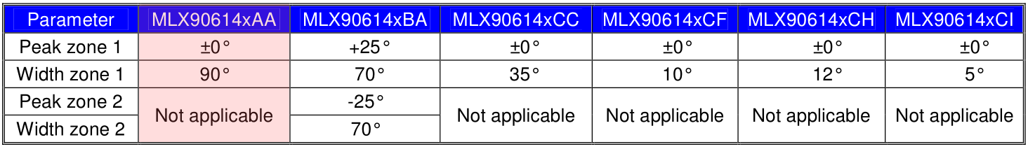
The variant also determines the field of view, which on the MLX90614BAA is 90°.
Speaking of which...
Field of View -- Distance vs. Spot Diameter
An IR thermometer's field-of-view (FOV) is a critical property to be aware of. It determines the relationship between the distance from an object and the area of space being observed. The MLX90614's field of view is cone-shaped -- its sensing area is very narrow if it's near the object, but gets increasingly wider as it moves farther away.
The MLX90614BAA has a relatively wide field-of-view angle: 90°. That means for every 1cm you move away from an object, the sensing area grows by 2cm. If you're one foot away from an object (30.48cm), the sensing area will be two feet (60.96cm).
Output Interfaces
The MLX90614 supports two interfaces -- though you'll need one to access the other. The two-wire SMBus interface is the primary means for communicating with the IR sensor. Once you've set up an SMBus interface, you can later configure the MLX90614 to produce a pulse-width modulated (PWM) signal representing the measured temperature(s).
SMBus (I2C)
The sensor is configured and read from over a 2-wire SMBus interface -- very similar, and nearly functionally equivalent to I2C. The two signals -- SDA and SCL -- carry the data and clock signals respectively. A master device controls the clock, while the data signal is bi-directionally controlled.
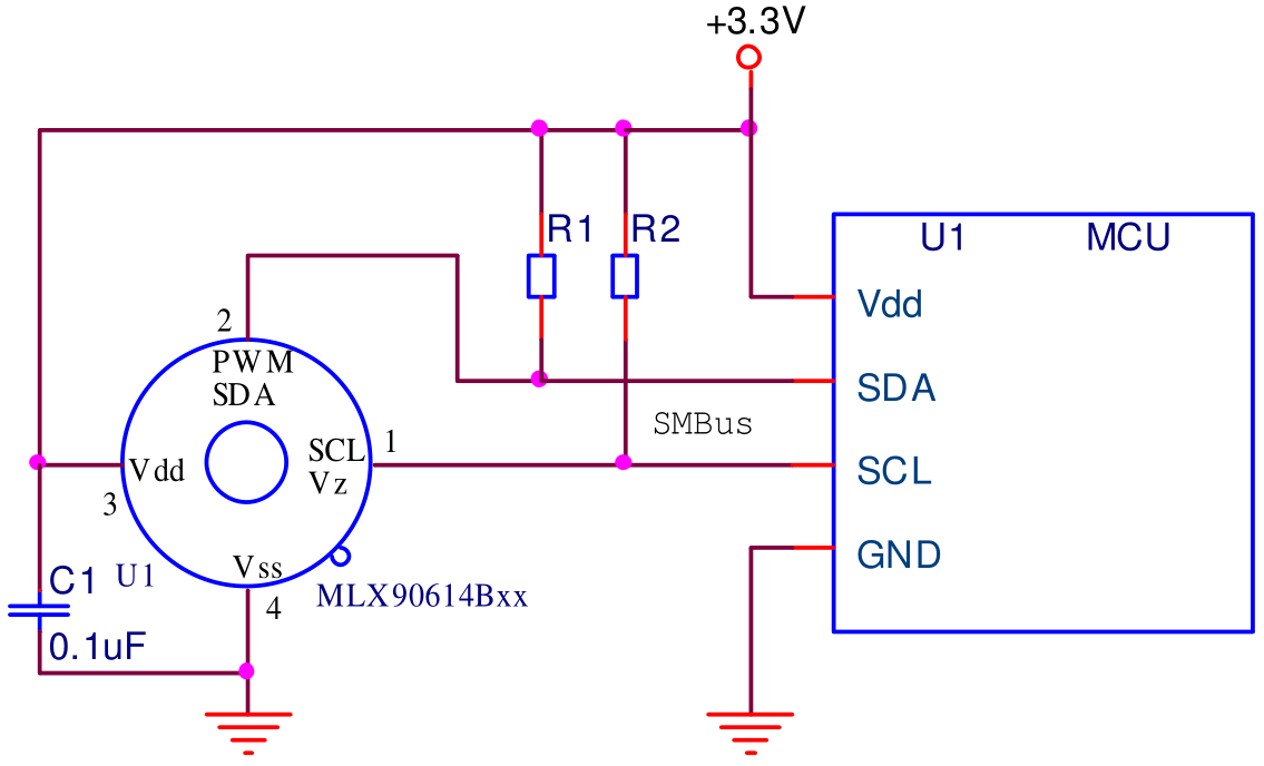
Every MLX90614 has a default I2C address of 0x5A, but that address can be re-written -- one of the major features supported by the device. By reconfiguring the address of an MLX90614, you can add multiple devices (up to 127!) to the same bus to get a larger temperature map.
One last bit to note about the SMBus interface -- every read or write transmission should be completed with an 8-bit CRC (CRC-8-CCITT) check using a x8+x2+x1+x0 polynomial -- handy for that extra bit of data-confidence.
PWM & "Thermal Relay"
The MLX90614's data can also be read via a PWM interface. In this use case just one wire is required to read from the sensor: SDA. To use the PWM interface, the MLX90614 has to be configured over the SMBus to produce it.
The PWM output can be difficult to use with a microcontroller, but it is very powerful if you want to use the MLX90614 to directly control a relay or other externally triggered device.
By configuring the sensor's range -- setting minimum and/or maximum temperature values -- the PWM output can be turned into a "thermal relay" signal. The PWM signal will be low unless the the object temperature exceeds the set threshold.
For a more exhaustive overview of the MLX90614, check out the datasheet.