MLX90614 IR Thermometer Hookup Guide
Evaluation Board Overview
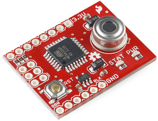
The SparkFun IR Thermometer Evaluation Board wires the MLX90614 up to an ATmega328 microprocessor so you can quickly begin developing with the sensor instead of fussing with wires and breadboards.
The ATmega328 on the Evaluation Board comes pre-programmed with UART-based example code, and an Arduino bootloader. After monitoring the temperature over the serial interface, you can use that same serial port to upload code of your own!
The Pinout
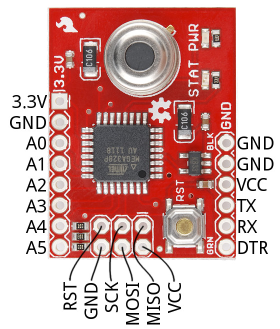
A pair of headers on opposite sides of the evaluation board break out a handful of microprocessor signals and power busses, and the ATmega's SPI interface is available on the ICSP header:
The pins are all labeled on the bottom side of the board, in case you don't want to refer back to this picture.
| Pin Label | Equivalent Arduino Pin | Notes |
|---|---|---|
| Serial Programming/Interface Header | ||
| GND | Ground (0v) | |
| GND | Ground (0v) | |
| VCC | Voltage supply input | |
| TX | 1 | UART input |
| RX | 0 | UART output |
| DTR | Auto-reset control from FTDI programmer | |
| GPIO/Power Header | ||
| 3.3V | 3.3V | 3.3V supply (regulated from the VCC input) |
| GND | GND | Ground (0v) |
| PC0 | A0 | Analog input and/or digital in/out |
| PC1 | A1 | Analog input and/or digital in/out |
| PC2 | A2 | Analog input and/or digital in/out |
| PC3 | A3 | Analog input and/or digital in/out |
| SDA | A4 | Serial data line to MLX90614 – more devices can be added to I2C bus. |
| SCL | A5 | Serial clock to MLX90614 – more devices can be added to I2C bus. |
| ICSP Header | ||
| RST | Reset | Arduino active-low reset |
| GND | GND | Ground (0v) |
| SCK | 13 | SPI clock and/or digital in/out |
| MOSI | 11 | SPI master-out/slave-in and/or digital in/out |
| MISO | 12 | SPI master-in/slave-out and/or digital in/out |
| VCC | 3.3V | 3.3V supply (regulated from the VCC input) |
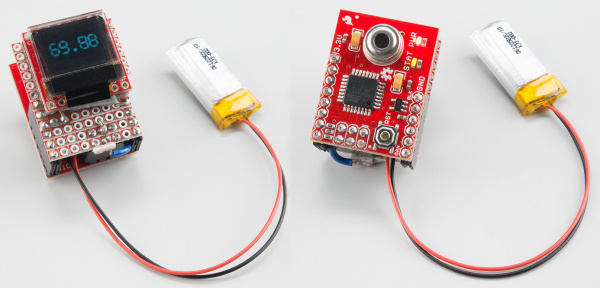
The extra GPIO allow you to build the "Evaluation Board" into a project centerpiece. With seven unused GPIO you can hookup Serial 7-Segment Displays, LCDs, or many other components. Plus, the I2C can be expanded with additional senors -- whether it's a light sensor or a motion sensor.
LED Indicators
The evaluation board has a green LED wired up to digital pin 8 (PB0). The LED is active-low, so writing the pin LOW will turn the LED on, and HIGH will turn it off.
The nearby red power LED should illuminate whenever the board is powered.


