Mini GPS Shield Hookup Guide
 Alex the Giant
Hardware Overview
Let's go over the Mini GPS Shield in detail.
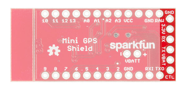
The Mini GPS Shield will work with any of our Arduino Mini boards. The board uses 3.3V logic, however the logic level converter on the shield allows you to use 5V boards just as easily.
Connecting the GPS
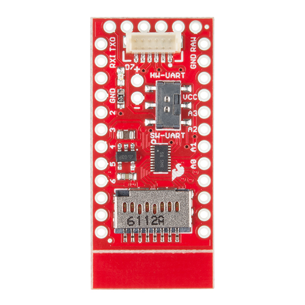
The shield comes with a 6-pin JST connector to connect the GP-735 GPS module. If you already have a GPS module, the JST pins are broken out and labeled to allow you to use just about any GPS module that works down to 3.3V.
NOTE: The RX and TX labels correspond to the data direction on the board. RX should be connected to the GPS TX pin and TX should be connected to the GPS RX pin.
Using the LED
One of the problems of GPS is the time it takes to get your first position reading. Each module is different, but a typical GPS fix takes around 30 seconds. Another downfall is getting a strong enough signal from the the satellites in orbit, which can increase the time it takes to get a position fix. Because of the uncertainty in the time it takes to get a position fix, we included an LED attached to digital pin 7. We'll see in the code below, how to use the LED to illuminate when we have locked in a position.
Software or Hardware Serial?
The GP-735 has a UART that makes communicating with the GPS very easy. Unfortunately, in many cases, the UART is tied up sending debug messages back to our computer. To get around this, we used software serial. Software serial, gives your microcontroller a software defined UART so you can communicate to your GPS while still sending the messages back to your computer. There are other times where you may need to use only the hardware serial, for example if your microcontroller is low on program memory. For this reason, we made switching between hardware and software serial easy, by including a switch that's labeled HW-UART for hardware serial on digital pins 0 and 1, and SW-UART for software serial on digital pins 4 and 5. You can learn more about serial communication here.
GPS Power Saving
The Mini GPS Shield was designed to work with the GP-735 GPS module. If you want to save power, you can pull digital pin 6 LOW, and it will disable power to the GPS. To enable power, you can either pull digital pin 6 HIGH or leave it floating.
The GP-735 does not have accessible non-volatile memory. This means that when you disconnect power, any settings (baud rate, update rate, etc) will not be saved. If you don't want to reconfigure these settings every time, you'll need to use a backup battery. The backup battery won't be used in the examples below, but, if you need to use it, those pins are labeled VBATT along with a "+" and "-" corresponding to the respective pins. The voltage of VBATT should be between 1.5V and 3.5V.
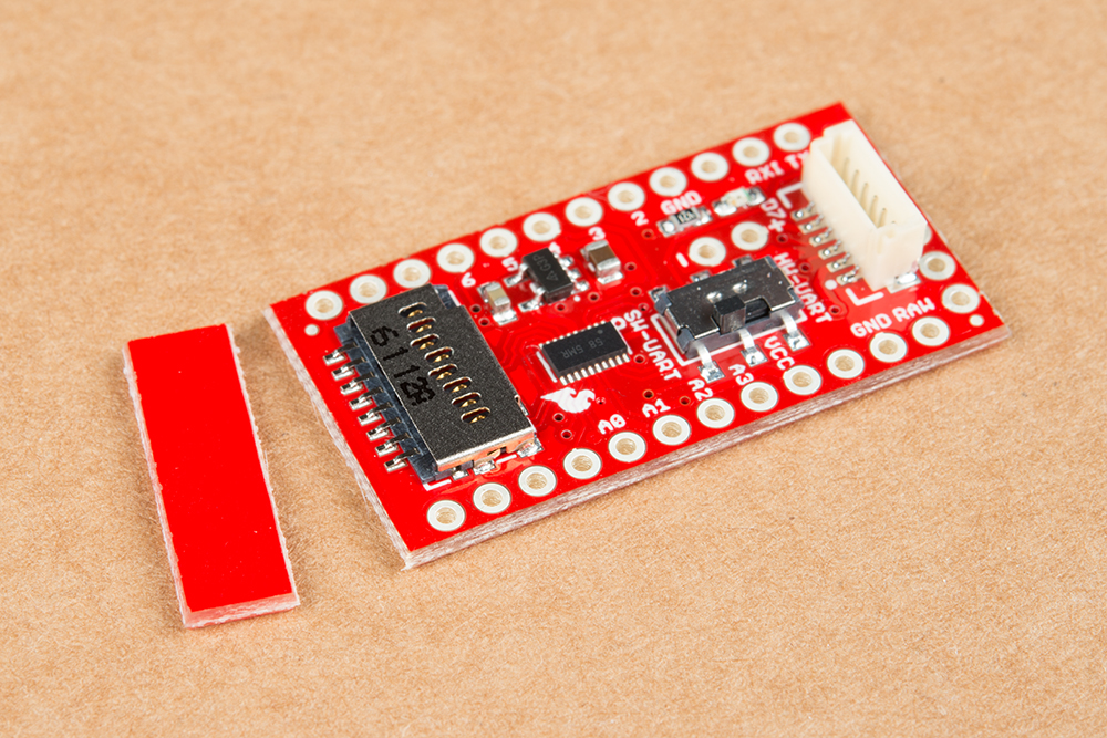
To Snap or not to Snap
You may have noticed the v-score next to the microSD connector. If you need the board to be as small as possible and aren't planning on using a microSD card, you can easily remove the extra board material by providing a little bit of force to bend the board and snap it off. If you are going to use an SD card, we recommend leaving it on so an accidental bump won't damage or dislodge your microSD card.