MicroMod Update Tool Hookup Guide
 El Duderino,
  PaulZC
 Introduction
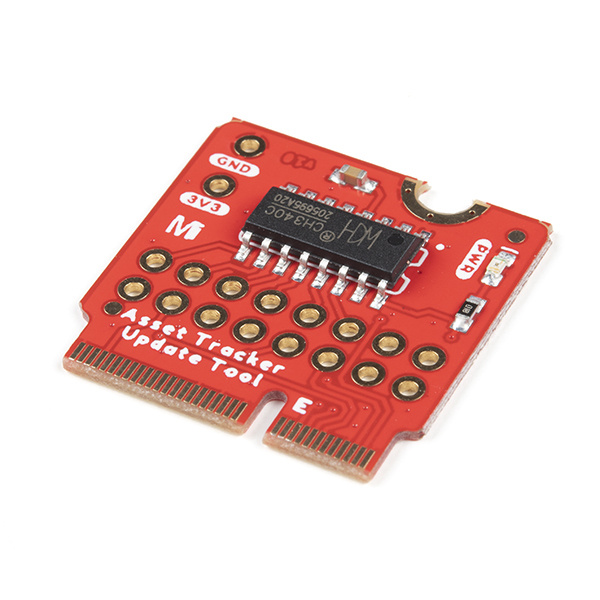
Introducing the SparkFun MicroMod Update Tool! This simple little board allows you to interact directly with the SARA-R5 LTE-M / NB-IoT module on the MicroMod Asset Tracker Carrier Board via the module's UART.
The MicroMod Asset Tracker Carrier Board provides you with a toolkit to monitor and track the location of your assets. Do you want to know where your assets are at all times? Or maybe you just want an update if an asset is moved? If so, this is the product for you!
Built around the u-blox SARA-R510M8S module, the asset tracker offers Secure Cloud LTE-M and NB-IoT data communication for multi-regional use and has an integrated u-blox M8 GNSS receiver for accurate positioning information. The SARA-R5 supports many different forms of data communication from full TCP/IP sockets and packet switched data, through HTTP Get/Put/Post, FTP (the SARA has a built-in file system), Ping, to good old SMS text messaging!
The Update Tool is not a full MicroMod Processor Board, it is much simpler than that. It has a CH340C USB-Serial converter on it which gives you full access to all eight pins of the SARA-R5's UART interface via the Asset Tracker’s USB-C connector. Think of it as a bridge from USB to serial.
Why is this a good idea? Well, for a start - as the name suggests - it is an ideal way to upgrade the SARA-R5’s firmware should you need to. The Update Tool also makes it simple to communicate directly with the SARA using u-blox’s sophisticated m-center cellular evaluation software. If you’re familiar with u-center, u-blox’s GNSS evaluation software, you’ll know how excellent their software is. m-center is every bit as good.
The Update Tool features eight pairs of Plated Through Hole connections for the UART signals. You can use these to connect directly to the SARA UART using 3.3V signals if you want to. The split pads on the rear of the Tool can be opened to isolate the CH340C completely; the pins nearest the M.2 will link straight to the SARA UART.
Required Materials
In order to follow along with this tutorial, you'll want to have the following items.
The Asset Tracker Firmware Update Tool, as the name suggests, is designed to work with the MicroMod Asset Tracker Carrier Board. The Update Tool along with a Hologram eUICC SIM Card are included with the Asset Tracker:
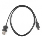
You'll also need a USB-C cable to connect the Carrier to your computer. Below are some options for USB cables:

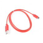
USB 2.0 Cable A to C - 3 Foot
CAB-15092
Optional Extras
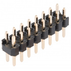
If you want to manipulate the UART connections on the Update Tool we recommend soldering a set of headers to your board. Below are a few options:

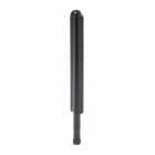
If you wish to use the Update Tool to interact directly with the SARA-R5 module on your Asset Tracker and do not have these items already, you may also need LTE and GNSS antennas:
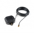
Suggested Reading
If you aren't familiar with the MicroMod ecosystem, we recommend reading here for an overview:
| MicroMod Ecosystem |
We also recommend reading through the following tutorials if you are not familiar with the concepts covered in them:
Serial Communication
How to Work with Jumper Pads and PCB Traces
How to Install CH340 Drivers
Getting Started with MicroMod
Hardware Overview
In this section we'll go over the hardware and components on the MicroMod Update Tool.
M.2 Connector
All of our MicroMod Processor boards come equipped with the M.2 MicroMod Connector, which leverages the M.2 standard and the Update Tool is no different. Just remember this is for use only with the MicroMod Asset Tracker Carrier Board.

|
 |
| M.2 Connector from the Front | M.2 Connector from the Back |
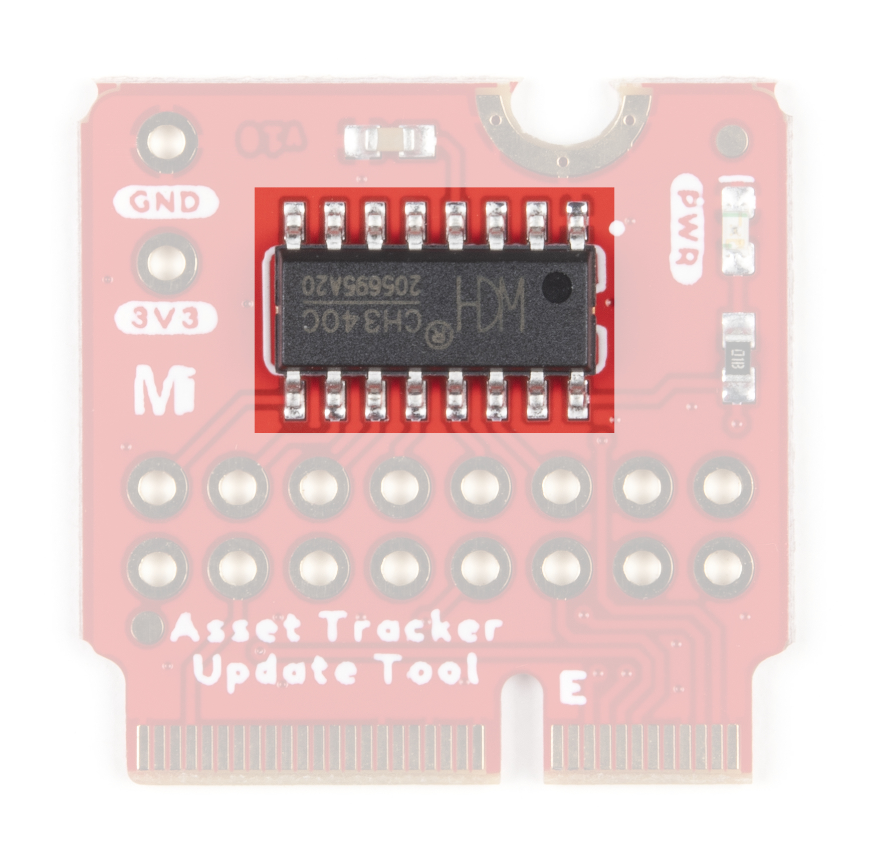
CH340 USB-Serial Converter
The heart of the Asset Tracker Firmware Update Tool is the CH340C USB-Serial converter which we use on many of our RedBoards and other breakouts. It converts 8-wire UART serial to USB.
PTH Connections and Jumpers
The Update Tool includes a set of eight jumpers to allow users to connect the SARA-R5 UART pins to a 3.3V development board. The jumpers can be opened to disconnect the pins from the CH340C to be re-routed to your development board.
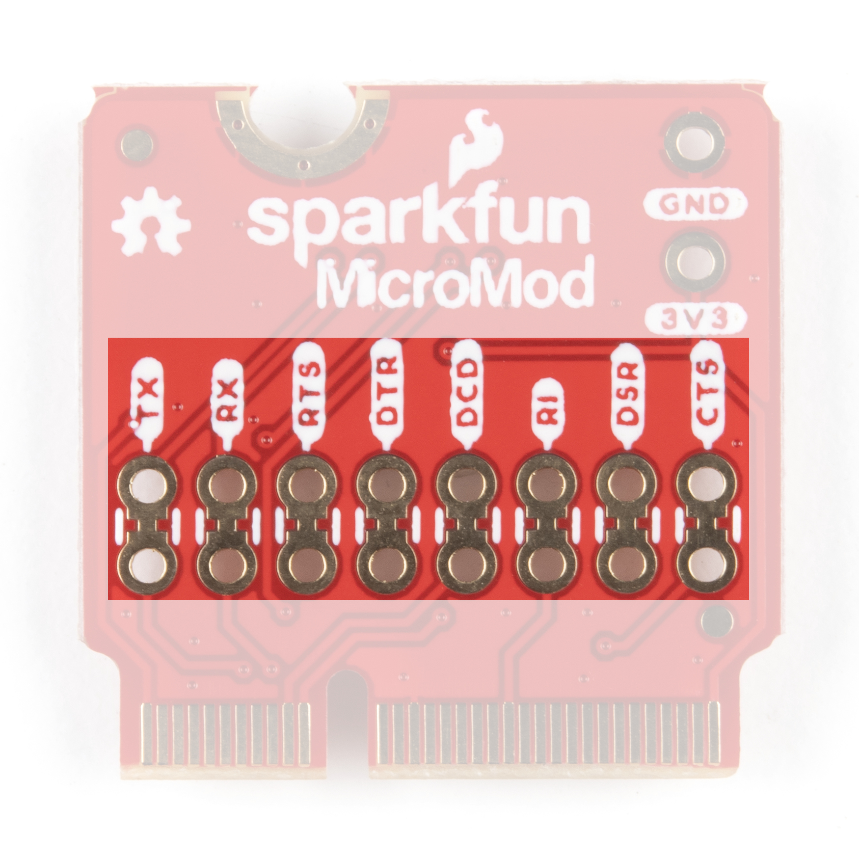
Take care to only connect the pins to a 3.3V RedBoard or Arduino Board or properly shift the logic level down to 3.3V. Connecting them to a 5V board may damage the Asset Tracker.
Read on to the Using the PTH Connections for more information.
MicroMod Update Tool Pin Functionality
Since the MicroMod Update Tool serves a specific purpose to communicate directly with the SARA-R5 on the MicroMod Asset Tracker Carrier Board, the pinout is much simpler than other MicroMod Processors. The tables below outline the pin functionality for the Update Tool along with the general MicroMod pinout. If you prefer to refer to the schematic it can be viewed here.
| AUDIO | UART | GPIO/BUS | I2C | SDIO | SPI | Dedicated |
| MicroMod Pin Number | Function | Asset Tracker Connection | Notes |
|---|---|---|---|
| 75 | GND | Ground | |
| 74 | 3.3V | 3.3V | |
| 69 | G7 | SARA DSR_O / RTS2_I | SARA Data Set Ready / AUX UART Request to Send |
| 48 | G4 | SARA RI_O / CTS2_O | SARA Ring Indicator / AUX UART Clear to Send |
| 22 | TX2 | SARA DTR_I / TXD2_I | SARA UART Data Terminal Ready / AUX UART Data Input |
| 20 | RX2 | SARA DCD_O / RXD2_O | SARA UART Data Carrier Detect / AUX UART Data Output |
| 19 | RX1 | SARA RXD_I | SARA UART Data Output |
| 17 | TX1 | SARA TXD_O | SARA UART Data Input |
| 15 | CTS1 | SARA CTS_O | SARA UART Clear to send |
| 13 | RTS1 | SARA RTS_I | SARA UART Request to send |
| 5 | USB_D- | USB-C | Passthrough to USB-C connector |
| 3 | USB_D+ | USB-C | Passthrough to USB-C connector |
| 2 | 3.3V | 3.3V | |
| 1 | GND | Ground |
| Function | Bottom Pin |
Top Pin |
Function | ||||||
|---|---|---|---|---|---|---|---|---|---|
| (Not Connected) | 75 | GND | |||||||
| 3.3V | 74 | 73 | G5 / BUS5 | ||||||
| RTC_3V_BATT | 72 | 71 | G6 / BUS6 | ||||||
| SPI_CS1# | SDIO_DATA3 (I/O) | 70 | 69 | G7 / BUS7 | |||||
| SDIO_DATA2 (I/O) | 68 | 67 | G8 | ||||||
| SDIO_DATA1 (I/O) | 66 | 65 | G9 | ADC_D- | CAM_HSYNC | ||||
| SPI_CIPO1 | SDIO_DATA0 (I/O) | 64 | 63 | G10 | ADC_D+ | CAM_VSYNC | |||
| SPI COPI1 | SDIO_CMD (I/O) | 62 | 61 | SPI_CIPO (I) | |||||
| SPI SCK1 | SDIO_SCK (O) | 60 | 59 | SPI_COPI (O) | LED_DAT | ||||
| AUD_MCLK (O) | 58 | 57 | SPI_SCK (O) | LED_CLK | |||||
| CAM_MCLK | PCM_OUT | I2S_OUT | AUD_OUT | 56 | 55 | SPI_CS# | |||
| CAM_PCLK | PCM_IN | I2S_IN | AUD_IN | 54 | 53 | I2C_SCL1 (I/O) | |||
| PDM_DATA | PCM_SYNC | I2S_WS | AUD_LRCLK | 52 | 51 | I2C_SDA1 (I/O) | |||
| PDM_CLK | PCM_CLK | I2S_SCK | AUD_BCLK | 50 | 49 | BATT_VIN / 3 (I - ADC) (0 to 3.3V) | |||
| G4 / BUS4 | 48 | 47 | PWM1 | ||||||
| G3 / BUS3 | 46 | 45 | GND | ||||||
| G2 / BUS2 | 44 | 43 | CAN_TX | ||||||
| G1 / BUS1 | 42 | 41 | CAN_RX | ||||||
| G0 / BUS0 | 40 | 39 | GND | ||||||
| A1 | 38 | 37 | USBHOST_D- | ||||||
| GND | 36 | 35 | USBHOST_D+ | ||||||
| A0 | 34 | 33 | GND | ||||||
| PWM0 | 32 | 31 | Module Key | ||||||
| Module Key | 30 | 29 | Module Key | ||||||
| Module Key | 28 | 27 | Module Key | ||||||
| Module Key | 26 | 25 | Module Key | ||||||
| Module Key | 24 | 23 | SWDIO | ||||||
| UART_TX2 (O) | 22 | 21 | SWDCK | ||||||
| UART_RX2 (I) | 20 | 19 | UART_RX1 (I) | ||||||
| CAM_TRIG | D1 | 18 | 17 | UART_TX1 (0) | |||||
| I2C_INT# | 16 | 15 | UART_CTS1 (I) | ||||||
| I2C_SCL (I/0) | 14 | 13 | UART_RTS1 (O) | ||||||
| I2C_SDA (I/0) | 12 | 11 | BOOT (I - Open Drain) | ||||||
| D0 | 10 | 9 | USB_VIN | ||||||
| SWO | G11 | 8 | 7 | GND | |||||
| RESET# (I - Open Drain) | 6 | 5 | USB_D- | ||||||
| 3.3V_EN | 4 | 3 | USB_D+ | ||||||
| 3.3V | 2 | 1 | GND | ||||||
| Signal Group | Signal | I/O | Description | Voltage | Power | 3.3V | I | 3.3V Source | 3.3V |
|---|---|---|---|---|
| GND | Return current path | 0V | ||
| USB_VIN | I | USB VIN compliant to USB 2.0 specification. Connect to pins on processor board that require 5V for USB functionality | 4.8-5.2V | |
| RTC_3V_BATT | I | 3V provided by external coin cell or mini battery. Max draw=100μA. Connect to pins maintaining an RTC during power loss. Can be left NC. | 3V | |
| 3.3V_EN | O | Controls the carrier board's main voltage regulator. Voltage above 1V will enable 3.3V power path. | 3.3V | |
| BATT_VIN/3 | I | Carrier board raw voltage over 3. 1/3 resistor divider is implemented on carrier board. Amplify the analog signal as needed for full 0-3.3V range | 3.3V | |
| Reset | Reset | I | Input to processor. Open drain with pullup on processor board. Pulling low resets processor. | 3.3V |
| Boot | I | Input to processor. Open drain with pullup on processor board. Pulling low puts processor into special boot mode. Can be left NC. | 3.3V | |
| USB | USB_D± | I/O | USB Data ±. Differential serial data interface compliant to USB 2.0 specification. If UART is required for programming, USB± must be routed to a USB-to-serial conversion IC on the processor board. | |
| USB Host | USBHOST_D± | I/O | For processors that support USB Host Mode. USB Data±. Differential serial data interface compliant to USB 2.0 specification. Can be left NC. | |
| CAN | CAN_RX | I | CAN Bus receive data. | 3.3V |
| CAN_TX | O | CAN Bus transmit data. | 3.3V | |
| UART | UART_RX1 | I | UART receive data. | 3.3V |
| UART_TX1 | O | UART transmit data. | 3.3V | |
| UART_RTS1 | O | UART request to send. | 3.3V | |
| UART_CTS1 | I | UART clear to send. | 3.3V | |
| UART_RX2 | I | 2nd UART receive data. | 3.3V | |
| UART_TX2 | O | 2nd UART transmit data. | 3.3V | |
| I2C | I2C_SCL | I/O | I2C clock. Open drain with pullup on carrier board. | 3.3V |
| I2C_SDA | I/O | I2C data. Open drain with pullup on carrier board | 3.3V | |
| I2C_INT# | I | Interrupt notification from carrier board to processor. Open drain with pullup on carrier board. Active LOW | 3.3V | |
| I2C_SCL1 | I/O | 2nd I2C clock. Open drain with pullup on carrier board. | 3.3V | |
| I2C_SDA1 | I/O | 2nd I2C data. Open drain with pullup on carrier board. | 3.3V | |
| SPI | SPI_COPI | O | SPI Controller Output/Peripheral Input. | 3.3V |
| SPI_CIPO | I | SPI Controller Input/Peripheral Output. | 3.3V | |
| SPI_SCK | O | SPI Clock. | 3.3V | |
| SPI_CS# | O | SPI Chip Select. Active LOW. Can be routed to GPIO if hardware CS is unused. | 3.3V | |
| SPI/SDIO | SPI_SCK1/SDIO_CLK | O | 2nd SPI Clock. Secondary use is SDIO Clock. | 3.3V |
| SPI_COPI1/SDIO_CMD | I/O | 2nd SPI Controller Output/Peripheral Input. Secondary use is SDIO command interface. | 3.3V | |
| SPI_CIPO1/SDIO_DATA0 | I/O | 2nd SPI Peripheral Input/Controller Output. Secondary use is SDIO data exchange bit 0. | 3.3V | |
| SDIO_DATA1 | I/O | SDIO data exchange bit 1. | 3.3V | |
| SDIO_DATA2 | I/O | SDIO data exchange bit 2. | 3.3V | |
| SPI_CS1/SDIO_DATA3 | I/O | 2nd SPI Chip Select. Secondary use is SDIO data exchange bit 3. | 3.3V | |
| Audio | AUD_MCLK | O | Audio master clock. | 3.3V |
| AUD_OUT/PCM_OUT/I2S_OUT/CAM_MCLK | O | Audio data output. PCM synchronous data output. I2S serial data out. Camera master clock. | 3.3V | |
| AUD_IN/PCM_IN/I2S_IN/CAM_PCLK | I | Audio data input. PCM syncrhonous data input. I2S serial data in. Camera periphperal clock. | 3.3V | |
| AUD_LRCLK/PCM_SYNC/I2S_WS/PDM_DATA | I/O | Audio left/right clock. PCM syncrhonous data SYNC. I2S word select. PDM data. | 3.3V | |
| AUD_BCLK/PCM_CLK/I2S_CLK/PDM_CLK | O | Audio bit clock. PCM clock. I2S continuous serial clock. PDM clock. | 3.3V | |
| SWD | SWDIO | I/O | Serial Wire Debug I/O. Connect if processor board supports SWD. Can be left NC. | 3.3V |
| SWDCK | I | Serial Wire Debug clock. Connect if processor board supports SWD. Can be left NC. | 3.3V | |
| ADC | A0 | I | Analog to digital converter 0. Amplify the analog signal as needed to enable full 0-3.3V range. | 3.3V |
| A1 | I | Analog to digital converter 1. Amplify the analog signal as needed to enable full 0-3.3V range. | 3.3V | |
| PWM | PWM0 | O | Pulse width modulated output 0. | 3.3V |
| PWM1 | O | Pulse width modulated output 1. | 3.3V | |
| Digital | D0 | I/O | General digital input/output pin. | 3.3V |
| D1/CAM_TRIG | I/O | General digital input/output pin. Camera trigger. | 3.3V | |
| General/Bus | G0/BUS0 | I/O | General purpose pins. Any unused processor pins should be assigned to Gx with ADC + PWM capable pins given priority (0, 1, 2, etc.) positions. The intent is to guarantee PWM, ADC and Digital Pin functionality on respective ADC/PWM/Digital pins. Gx pins do not guarantee ADC/PWM function. Alternative use is pins can support a fast read/write 8-bit or 4-bit wide bus. | 3.3V |
| G1/BUS1 | I/O | 3.3V | ||
| G2/BUS2 | I/O | 3.3V | ||
| G3/BUS3 | I/O | 3.3V | ||
| G4/BUS4 | I/O | 3.3V | ||
| G5/BUS5 | I/O | 3.3V | ||
| G6/BUS6 | I/O | 3.3V | ||
| G7/BUS7 | I/O | 3.3V | ||
| G8 | I/O | General purpose pin | 3.3V | |
| G9/ADC_D-/CAM_HSYNC | I/O | Differential ADC input if available. Camera horizontal sync. | 3.3V | |
| G10/ADC_D+/CAM_VSYNC | I/O | Differential ADC input if available. Camera vertical sync. | 3.3V | |
| G11/SWO | I/O | General purpose pin. Serial Wire Output | 3.3V |
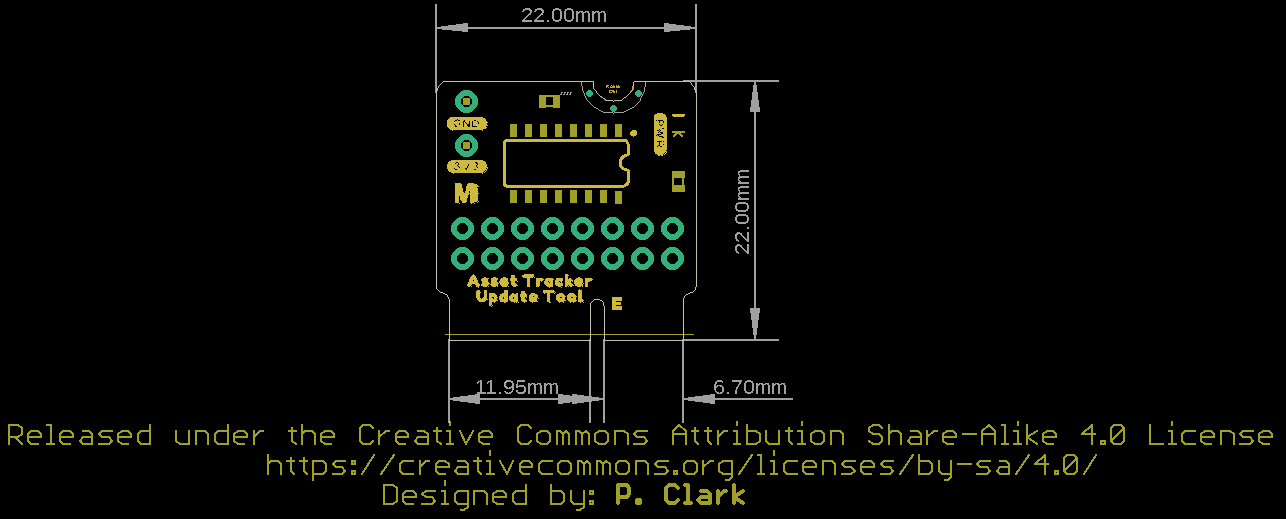
Board Dimensions
The board measures 22mm x 22mm, with 15mm to the top notch and 12mm to the E key. For more information regarding the processor board physical standards, head on over to the Getting Started with MicroMod tutorial and check out the Hardware Overview section.
Hardware Assembly
Inserting your Update Tool
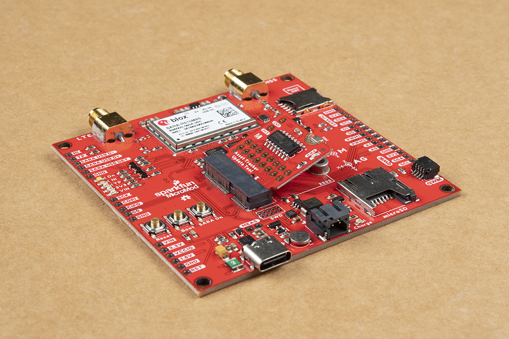
With the M.2 MicroMod connector, connecting your Update Tool to the Asset Tracker is a breeze. Simply match up the key on your Processor's beveled edge connector to the key on the M.2 connector. At a 45° angle, insert the processor board to the M.2 connector. The Update Tool will stick up at an angle as seen here:
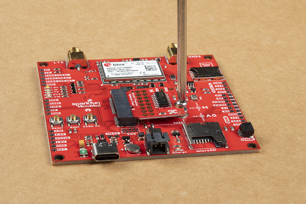
Once the update tool is in the socket, gently press the board down, grab the set screw and tighten it with a Phillip's head screwdriver:
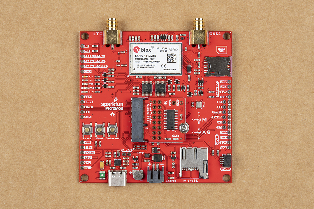
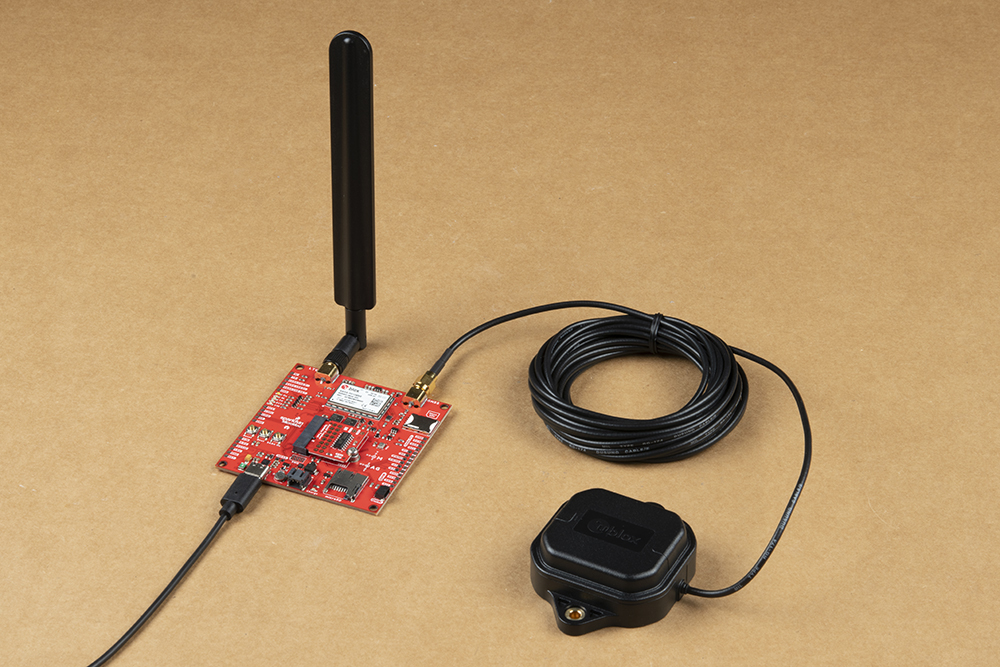
Once the Update Tool is secure, your assembled MicroMod Asset Tracker system should look similar to the image below!
Connecting Everything Up
Now is a good time to insert the Nano SIM from your service provider into the Asset Tracker. Make sure the orientation matches the symbol on the PCB; the edge with the trimmed corner is inserted first.
The LTE and GNSS connections simply screw on to the appropriate SMA connectors. Make sure you check the labelling and connect them the right way round. LTE is on the Left.
With your Update Tool inserted and secured it's time to connect your MicroMod Asset Tracker Carrier Board to your computer using the USB-C connector. Depending on which drivers you already have installed, you may need to install drivers for the CH340. Please refer to our CH340 tutorial for further instructions.
Software Setup
Installing u-blox m-center
You can find the webpage for u-blox's m-center software here. Sadly m-center is only available for Windows and we don’t know of an equivalent for Linux. This link will download version 2.03.0 of m-center (but please do check the u-blox website for more recent versions):
Unzip the file and run the m-center .EXE to install the software.
Using u-blox m-center
Like u-center, m-center is very easy and intuitive to use. Let's go over the features of the software.
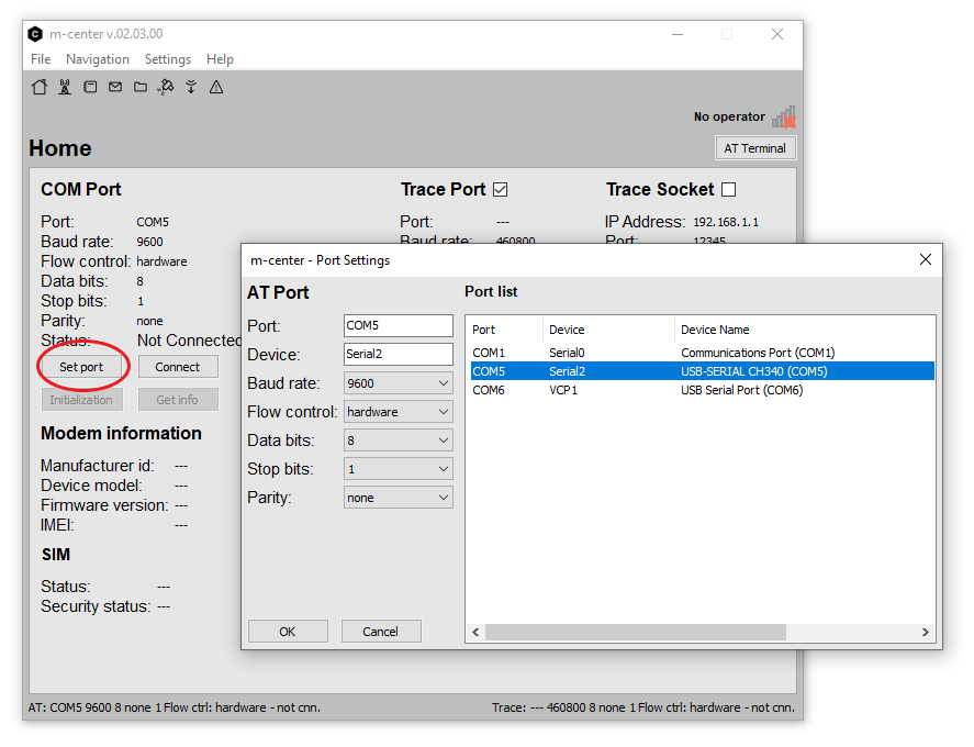
Home
Begin by clicking Set port and selecting the port for the CH340 Update Tool:
Click Connect, followed by Initialization to connect to the SARA-R5. The IMEI and firmware version should appear:
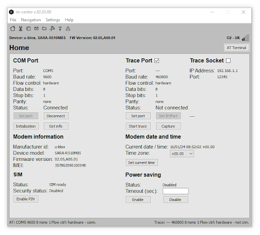
The carrier operator name and signal strength will appear in the top right corner of the window. We are told by u-blox that it is normal for the signal strength to appear quite low; LTE communication works with relatively low signal levels.
We believe the Trace Port option can be used to connect to the SARA-R5's USB diagnostic port via the SARA USB D+/D-/DET pins on the Asset Tracker Carrier Board, but we have not tried that yet.
Click Set current time to set the SARA's internal clock from the LTE network.
Network
Click the Network icon, next to the Home icon in the top left of the window, to see the network operator settings.
Click Refresh Info, Get List and Refresh to update the network information and Packet Switched Data Profiles.

You can choose to deregister from the current operator and connect to a new one if your SIM supports it.
You can also activate and deactivate the Packet Switched Data profile from this page. You will not able to send and receive data until you have activated a profile.
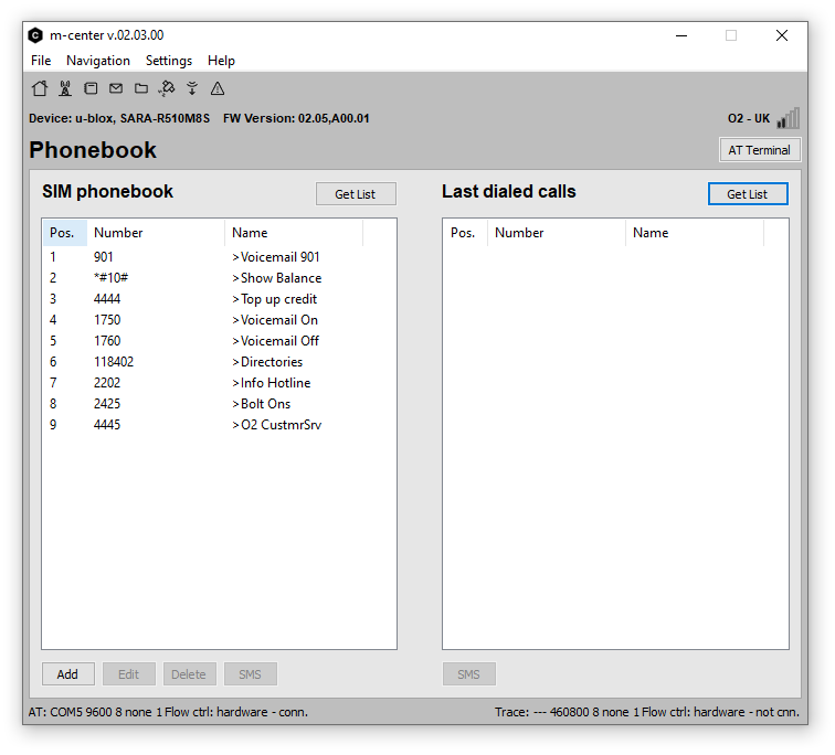
Phonebook
As the name suggests, the phonebook icon opens the SARA’s phonebook. You can add and delete numbers here.
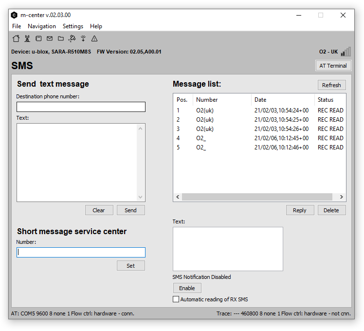
SMS
The SMS (envelope) icon will allow you to send text messages and read or reply to any received messages.
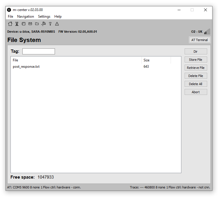
File System
The File System icon provides access to the SARA’s internal file system. You can add, retrieve and delete files from here. If you have run the Asset Tracker ThingSpeak (HTTP POST) example, the results of the most recent POST are stored in post_response.txt.
Did you know that the SARA-R5 supports FTP transfer too? Of course it does...
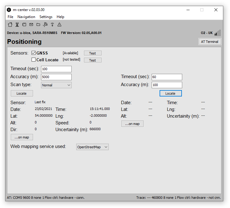
Positioning
The Positioning icon provides access to positioning information derived from either the LTE network, or the SARA-R510M8S’s built-in M8 GNSS receiver.
Firmware Over the Air (FOTA) and eCall Simulator
Advanced users can make use of the SARA’s Firmware download Over The Air and eCall Simulation functions:

AT Terminal
One of the most important features offered by m-center is the AT Terminal. Clicking the button below the signal strength indicator opens a Pandora’s Box full of AT Command goodies!
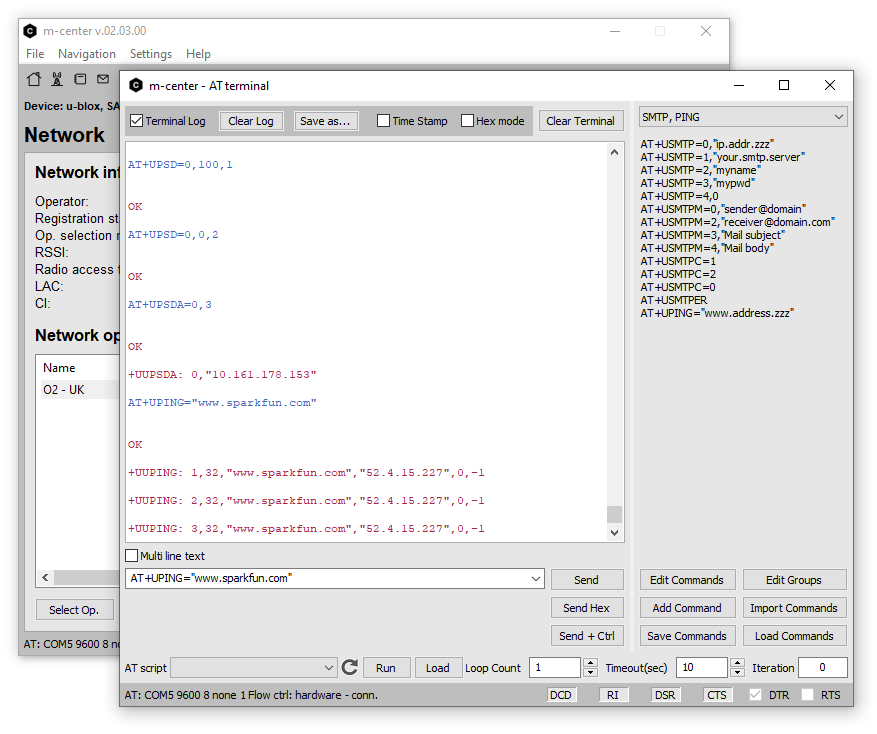
You can either type the AT commands manually into the text box, or select a template message from the drop-down menus, and then click Send or hit Enter to send the message. The replies from the SARA are shown in the Terminal window. You can log everything to file too if you wish. Scripts? Yes, you can run those too! This is a very powerful tool.
To manually Ping a server (such as www.sparkfun.com) the truncated set of commands is:
- AT+UPSD=0,100,1
- This instructs the SARA to map the Context ID 1 profile into Profile ID 0.
- AT+UPSD=0,0,2
- This instructs the SARA to use the “IPv4v6 with IPv4 preferred” protocol for Profile ID 0 (this needs to match the operator’s protocol).
- AT+UPSDA=0,3
- This instructs the SARA to activate Profile ID 0.
- AT+UPING="www.sparkfun.com"
- This instructs the SARA to ping the SparkFun server
Upgrading the SARA Firmware with u-blox EasyFlash
Just about the only thing that m-center doesn’t allow you to do is to upgrade the SARA-R5’s firmware. To do that you need to download and install u-blox’s EasyFlash update tool.

The link below will download EasyFlash version 12.08 but do check the SARA-R5 resources page for the latest version as of this writing:
Again, EasyFlash only appears to be available for Windows. We are not aware of a version for Linux. Unzip the .ZIP file and run the EasyFlash .MSI installer to install the software. u-blox will make the firmware updates available through the SARA-R5 resources page.
You need to manually download the .DOF update binary file and place it in the same folder as the EasyFlash executable. (That bit is important!). After the .DOF file is downloaded follow these steps:
- Run the EasyFlash executable.
- Select SARA-R5 as the Product.
- Select the COM port your Firmware Update Tool (CH340) is connected to.
- Select 921600 as the Baud Rate.
- Do not select 3000000 Baud as the CH340 cannot support it.
- Turn the SARA-R5 off by pushing and holding the SARA On button on the Asset Tracker for five seconds.
- Check that the white On LED on the Asset Tracker goes out.
- Click the Start button on EasyFlash.
- Press the SARA On button briefly when instructed to turn the SARA back on again.
- The update process takes around three minutes to complete.
- Turn the SARA off again when instructed to complete the update.

|
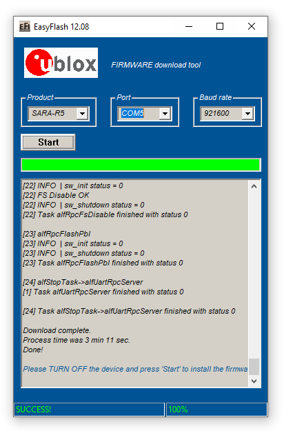
|
| Firmware update in progress | Firmware update completed |
You can confirm that the update was successful by opening m-center and connecting to the SARA-R5. The firmware version is shown on the Home page:

Using the PTH Connections
Want to connect the SARA UART pins to your favourite 3.3V RedBoard or Arduino Board? The Firmware Update Tool lets you do that too!
If you flip the Update Tool over, you will see eight jumpers linking each pair of Plated Through Holes. You can cut the jumpers to disconnect the PTHs from the CH340C. You can then connect the holes closest to the M.2 connector to your 3.3V board.
Insert 1x8 or 2x8 0.1”-pitch header pins through the front of the Firmware Update Tool and solder them on the back. 2x8 header pins are a good idea as it means you can use header jumper links to reconnect the CH340C again if you want to.

- Take care when selecting which header pins to solder onto the Update Tool. The pins must not protrude from the back of the board by more than 1.25mm or they will collide with the IMU and other components on the Asset Tracker circuit board. Trim the pins if necessary before soldering.
- Take care to only connect the pins to a 3.3V RedBoard or Arduino Board or properly shift the logic level down to 3.3V. Connecting them to a 5V board may damage the Asset Tracker.
Troubleshooting
Below we have outlined a few troubleshooting tips for the MicroMod Update Tool and MicroMod Asset Tracker Carrier Board.
LTE Network Availability
The SARA-R5 supports LTE-M and NB-IoT data communication for multi-regional use. Please check the LTE signal availability for your area before purchasing a SARA-R5 product and selecting an LTE service provider / operator.
TP (1PPS) Pin and LED
At the time of writing, we are shipping the SARA-R5 on the Asset Tracker with firmware version 02.06 on it. 02.06 contains a feature (which is just a polite name for a bug!) which means the 1 Pulse-Per-Second from the GNSS does work, but the pulse is only ~3 microseconds wide and cannot be adjusted. Handy huh? u-blox are aware of this - in fact we told them about it - and a fix is coming but they haven’t added it yet. We will keep an eye out for this fix and update this page when it is available.
Just to complicate matters, 3 microseconds is too short for the buffer FET and LED connected to the timing pulse to respond. So, we regret that you cannot currently use the TP PTH. We will share the fix with you as soon as we have it. The SARA firmware is easy to update using the Asset Tracker Firmware Update Tool.
General Troubleshooting
If you need technical assistance and more information on a product that is not working as you expected, we recommend heading on over to the SparkFun Technical Assistance page for some initial troubleshooting.
If you don't find what you need there, the SparkFun Forums: MicroMod are a great place to find and ask for help. If this is your first visit, you'll need to create a Forum Account to search product forums and post questions.
Resources and Going Further
Want more information on the MicroMod Update Tool? Check out these links!
u-blox Documentation and Software:
MicroMod Documentation:
If you have not already, be sure to check out our Hookup Guide for the Asset Tracker Carrier Board: