MicroMod Main Board Hookup Guide V2
 bboyho,
  Elias The Sparkiest
Arduino Examples
Let's go over a few basic examples to get started with the MicroMod Main Board Single and Double. We'll toggle the 3.3V voltage regulators and log data to a microSD card on both boards.
Example 1: MicroMod Main Board - Single Enable Function Board
If you have not already, select your Board (in this case the MicroMod Artemis), and associated COM port. Copy and paste the code below in your Arduino IDE. Hit the upload button.
language:c
/******************************************************************************

  WRITTEN BY: Ho Yun "Bobby" Chan
  @ SparkFun Electronics
  UPDATED: 1/3/2023
  DATE: 10/19/2021
  GITHUB REPO: https://github.com/sparkfun/SparkFun_MicroMod_Main_Board_Single
  DEVELOPMENT ENVIRONMENT SPECIFICS:
    Firmware developed using Arduino IDE v1.8.12

  ========== DESCRIPTION==========
  This example code toggles the Function Board's AP2112 3.3V voltage
  regulator's enable pin. The Function Boards built-in power LED should blink.
  This example is based on Arduino's built-in Blink Example:

      https://www.arduino.cc/en/Tutorial/BuiltInExamples/Blink

  Note that this example code uses the MicroMod Main Board - Single. The MicroMod
  Main Board - Double routes the PWR_EN# pins slightly different for the
  two function boards.

  ========== HARDWARE CONNECTIONS ==========
  MicroMod Artemis Processor Board => MicroMod Main Board - Single => Function Board

  Feel like supporting open source hardware?
  Buy a board from SparkFun!
       MicroMod Artemis Processor Board - https://www.sparkfun.com/products/16401
       MicroMod Main Board - Single - https://www.sparkfun.com/products/20748
       MicroMod Environmental Function Board - https://www.sparkfun.com/products/18632

  LICENSE: This code is released under the MIT License (http://opensource.org/licenses/MIT)

******************************************************************************/

/*Define the power enable pins for the processor board with either SDIO_DATA2 or A1.
  Depending on the processor board, the Arduino pin may be different.

  Note: For MicroMod Main Board - Single v2.1, there is now only one GPIO available
        to toggle the Power Enable 0 (PWR_EN0) pin. The previous defines for a few
        Processor Boards are still available for those that have v1.1.

        For MicroMod Main Board - Single v1.1, certain Processor Boards like the
        Artemis have SDIO_DATA2 and A1 available to control the Function Board's
        voltage regulator. SAMD51, ESP32, and STM32 Processor Board pins do not
        have SDIO_DATA2, so users will need to reference the Processor Pin A1.
        Below are a few examples.*/


//==========ARTEMIS==========
//Function Board 0's "PWR_EN0" pin <= MicroMod Main - Single v2.1 PWM1 => Artemis Processor Board (D45)
#define PWR_EN0 45

//Function Board 0's "PWR_EN0" pin <= MicroMod Main - Single v1.1 SDIO_DATA2 => Artemis Processor Board (D4)
//#define PWR_EN0 4

//Alternative option that does the same thing. Make sure to just choose one for PWR_EN0
//Function Board 0's "PWR_EN0" pin <= MicroMod Main - Single v1.1 A1 => Artemis Processor Board (A35)
//#define PWR_EN0 35


//==========TEENSY==========
//Function Board 0's "PWR_EN0" pin <= MicroMod Main- Single v2.1 PWM1 => Teensy Processor Board (2)
//#define PWR_EN0 2

//Function Board 0's "PWR_EN0" pin <= MicroMod Main - Single v1.1 SDIO_DATA2 => Teensy Processor Board (39)
//#define PWR_EN0 39

//Alternative option that does the same thing. Make sure to just choose one for PWR_EN0
//Function Board 0's "PWR_EN0" pin <= MicroMod Main - Single v1.1 A1 => Teensy Processor Board (A1)
//#define PWR_EN0 15


//Note: For those using Main - Single v1.1;
//      SAMD51, ESP32, and STM32 Processor Board Pins
//      do not have SDIO_DATA2 and SDIO_DATA1.

//==========SAMD51==========
//Function Board 0's "PWR_EN0" pin <= MicroMod Main - Single v2.1 PWM1 => SAMD51 Processor Board (20)
//#define PWR_EN0 20

//Function Board 0's "PWR_EN0" pin <= MicroMod Main - Single v1.1 A1 => SAMD51 Processor Board (18)
//#define PWR_EN0 18


//==========ESP32==========
//Function Board 0's "PWR_EN0" pin <= MicroMod Main - Single v2.1 PWM1 => ESP32 Processor Board (12)
//#define PWR_EN0 12

//Function Board 0's "PWR_EN0" pin <= MicroMod Main - Single v1.1 A1 => ESP32 Processor Board (35)
//#define PWR_EN0 35


void setup() {
  // initialize the digital pin as an output.
    pinMode(PWR_EN0, OUTPUT);
}


void loop() {
  digitalWrite(PWR_EN0, HIGH); // turn the 3.3V regulator on (HIGH is the voltage level)
  delay(5000);                 // wait for a few seconds to do something with the function boards

  digitalWrite(PWR_EN0, LOW);  // turn the 3.3V regulator off by making the voltage LOW
  delay(5000);                 // wait for a few seconds before turning function boards back on

}
After uploading, take a look at your Function Board's PWR LED. The LED will be on for about 5 seconds and then turn off for another 5 seconds. It will continue to repeat until power is removed from the MicroMod Main Board - Single.
Example 2: MicroMod Main Board - Double Enable Function Boards
If you have not already, select your Board (in this case the MicroMod Artemis), and associated COM port. Copy and paste the code below in your Arduino IDE. Hit the upload button.
language:c
/******************************************************************************

  WRITTEN BY: Ho Yun "Bobby" Chan
  @ SparkFun Electronics
  UPDATED: 1/3/2023
  DATE: 10/19/2021
  GITHUB REPO: https://github.com/sparkfun/SparkFun_MicroMod_Main_Board_Double
  DEVELOPMENT ENVIRONMENT SPECIFICS:
    Firmware developed using Arduino IDE v1.8.12

  ========== DESCRIPTION==========
  This example code toggles the Function Board's AP2112 3.3V voltage
  regulator's enable pin. The Function Boards built-in power LED should blink.
   This example is based on Arduino's built-in Blink Example:

      https://www.arduino.cc/en/Tutorial/BuiltInExamples/Blink

  Note that this example code uses the MicroMod Main Board - Double. The MicroMod
  Main Board - Single routes the PWR_EN0 pin slightly different for the
  function board.

  ========== HARDWARE CONNECTIONS ==========
  MicroMod Artemis Processor Board => MicroMod Main Board - Double => Function Boards

  Feel like supporting open source hardware?
  Buy a board from SparkFun!
       MicroMod Artemis Processor Board - https://www.sparkfun.com/products/16401
       MicroMod Main Board - Double - https://www.sparkfun.com/products/20595
       MicroMod Environmental Function Board - https://www.sparkfun.com/products/18632

  LICENSE: This code is released under the MIT License (http://opensource.org/licenses/MIT)

******************************************************************************/

/*Define the power enable pins for the processor board with SDIO_DATA2 and SDIO_DATA1.
  Depending on the processor board, the Arduino pin may be different.

  Note: Certain Processor Boards like the Artemis have more than one pin available
        to control the Function Board's voltage regulator (e.g. SDIO_DATA2 and G5).
        SAMD51, ESP32, and STM32 Processor Board pins do not have SDIO_DATA2, so
        users will need to reference the Processor Pin G5. Below are a few examples. */

//==========ARTEMIS==========
// We suggest flipping the switch to the G5 PROC and G6 PROC. The volrage regulators will work reguardless
// since SDIO_DATA2 and SDIO_DATA1 are connected regardless of what side the switch is on.
// Function Board 0's "PWR_EN0" pin <= MicroMod Main - Double SDIO_DATA2 => Artemis Processor Board (D4)
#define PWR_EN0 4
// Function Board 1's "PWR_EN1" pin <= MicroMod Main - Double SDIO_DATA1 => Artemis Processor Board (D26)
#define PWR_EN1 26

// Make sure switch is flipped over to the EN0 ALT and & EN1 ALT.
// Alternative option that does the same thing. Make sure to just choose one for PWR_EN0 and PWR_EN1.
// Function Board 0's "PWR_EN0" pin <= MicroMod Main - Double G5 => Artemis Processor Board (A29)
//#define PWR_EN0 29
// Function Board 1's "PWR_EN0" pin <= MicroMod Main - Double G6 => Artemis Processor Board (D14)
//#define PWR_EN1 14


//==========TEENSY==========
// We suggest flipping the switch to the G5 PROC and G6 PROC. The volrage regulators will work reguardless
// since SDIO_DATA2 and SDIO_DATA1 are connected regardless of what side the switch is on.
// Function Board 0's "PWR_EN0" pin <= MicroMod Main - Double SDIO_DATA2 => Teensy Processor Board (D39)
//#define PWR_EN0 39
// Function Board 1's "PWR_EN1" pin <= MicroMod Main - Double SDIO_DATA1 => Teensy Processor Board (D34)
//#define PWR_EN1 34

// Make sure switch is flipped over to the EN0 ALT and & EN1 ALT.
// Alternative option that does the same thing. Make sure to just choose one for PWR_EN0 and PWR_EN1
// Function Board 0's "PWR_EN0" pin <= MicroMod Main - Double G5 => Teensy Processor Board (45)
//#define PWR_EN0 45
// Function Board 1's "PWR_EN1" pin <= MicroMod Main - Double G6 => Teensy Processor Board (6)
//#define PWR_EN1 6


//Note: The SAMD51, ESP32, and STM32 Processor Board Pins do not have SDIO_DATA2 and SDIO_DATA1.

//==========SAMD51==========
// Make sure switch is flipped over to the EN0 ALT and & EN1 ALT.
// Function Board 0's "PWR_EN0" pin <= MicroMod Main - Double G5 => SAMD51 Processor Board (D7)
//#define PWR_EN0 7
//Function Board 1's"PWR_EN1" pin <= MicroMod Main - Double G6 => SAMD51 Processor Board (D8)
//#define PWR_EN1 8


//==========ESP32==========
// Make sure switch is flipped over to the EN0 ALT and & EN1 ALT.
// Function Board 0's "PWR_EN0" pin <= MicroMod Main - Double G5 => ESP32 Processor Board (32)
//#define PWR_EN0  32
// Function Board 1's"PWR_EN1" pin <= MicroMod Main - Double G6 => ESP32 Processor Board (33)
//#define PWR_EN1  33


void setup() {
  // initialize the digital pins as an output.
  pinMode(PWR_EN0, OUTPUT);
  pinMode(PWR_EN1, OUTPUT);

}


void loop() {

  digitalWrite(PWR_EN0, HIGH); // turn the 3.3V regulator on (HIGH is the voltage level)
  digitalWrite(PWR_EN1, HIGH); // turn the 3.3V regulator on (HIGH is the voltage level)
  delay(5000);                 // wait for a few seconds to do something with the function boards

  digitalWrite(PWR_EN0, LOW);  // turn the 3.3V regulator off by making the voltage LOW
  digitalWrite(PWR_EN1, LOW);  // turn the 3.3V regulator off by making the voltage LOW
  delay(5000);                 // wait for a few seconds before turning function boards back on

}
After uploading, take a look at the PWR LEDs on the Function Boards. The LEDs will be on for about 5 seconds and then turn off for another 5 seconds. It will continue to repeat until power is removed from the MicroMod Main Board - Double.
Example 3: Reading and Writing to a MicroSD Card
const int chipSelect = 10;//==========TEENSY==========
// default value used in Teensy SD Example Code
//const int chipSelect = 10;
// The microSD Card CS pin is D1 for the MicroMod Main Board - Single and Teensy Processor (5). Adjust for your processor if necessary.
const int chipSelect 5;
// The microSD Card's CS pin is G4 for the MicroMod Main Board - Double and Teensy Processor (44). Adjust for your processor if necessary.
//const int chipSelect 44;The example below uses the built-in SD Arduino library. The only difference in the code is the CS pin for the microSD card, which you will need to adjust for your processor board (in this case we use the Artemis Processor Board). Make sure to reference your Processor Board's CS pin for either the Main Board - Single (D1) or Main Board - Double (G4).
If you have not already, select your Board (in this case the MicroMod Artemis), and associated COM port. Copy and paste the code below in your Arduino IDE. Hit the upload button.
language:c
/*
  SD Card Read/Write

  This example shows how to read and write data to and from an SD card file
  The circuit:

  SD card attached to SPI bus as follows:

   SD Card   <=> MicroMod Main Board <=> Artemis Processor Board
   -----------------------------------------------------------------
   SD ENABLE <=>  I2C_SDA1-PROCESSOR <=> pin 9
   PICO/SDO  <=>  SPI_PROCESSOR_SDO  <=> pin 38
   POCI/SDI  <=>  SPI_PROCESSOR_SDI  <=> pin 43
   CLK       <=>  SPI_PROCESSOR_CLK  <=> pin 42
   CS        <=>  D1_PROCESSOR       <=> pin 1 (Main Board - Single)
   or ...
   CS        <=>  G4_PROCESSOR       <=> pin 28 (Main Board - Double)

  created   Nov 2010
  by David A. Mellis
  modified 9 Apr 2012
  by Tom Igoe

  This example code is in the public domain.

*/

#include <SPI.h>
#include <SD.h>

//==========ARTEMIS==========
// The microSD Card CS pin is D1 for the MicroMod Main Board - Single and Artemis Processor (D1). Adjust for your processor if necessary.
const int SD_CS_PIN = 1;
// The microSD Card's CS pin is G4 for the MicroMod Main Board - Double and Artemis Processor (D28). Adjust for your processor if necessary.
//const int SD_CS_PIN = 28;

File myFile;

void setup() {
  // Open serial communications and wait for port to open:
  Serial.begin(9600);
  while (!Serial) {
    ; // wait for serial port to connect. Needed for native USB port only
  }


  Serial.print("Initializing SD card...");

  if (!SD.begin(SD_CS_PIN)) {
    Serial.println("initialization failed!");
    while (1);
  }
  Serial.println("initialization done.");

  // open the file. note that only one file can be open at a time,
  // so you have to close this one before opening another.
  myFile = SD.open("test.txt", FILE_WRITE);

  // if the file opened okay, write to it:
  if (myFile) {
    Serial.print("Writing to test.txt...");
    myFile.println("testing 1, 2, 3.");
    // close the file:
    myFile.close();
    Serial.println("done.");
  } else {
    // if the file didn't open, print an error:
    Serial.println("error opening test.txt");
  }

  // re-open the file for reading:
  myFile = SD.open("test.txt");
  if (myFile) {
    Serial.println("test.txt:");

    // read from the file until there's nothing else in it:
    while (myFile.available()) {
      Serial.write(myFile.read());
    }
    // close the file:
    myFile.close();
  } else {
    // if the file didn't open, print an error:
    Serial.println("error opening test.txt");
  }
}

void loop() {
  // nothing happens after setup
}
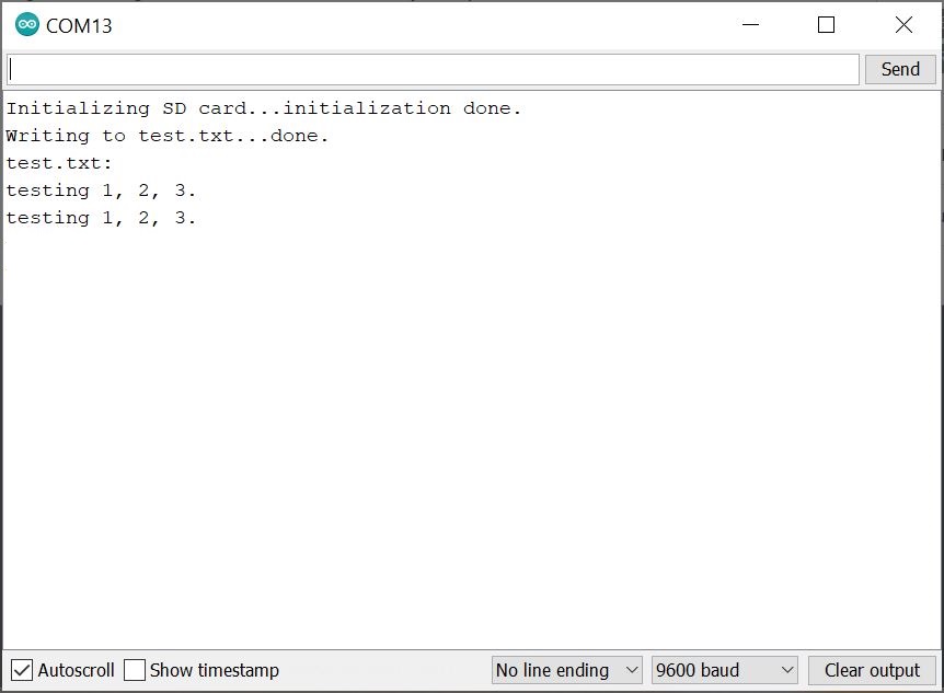
Open the Arduino Serial Monitor at 9600 baud. If all goes well, you should see the following output if this is the first time writing to the card! Note that you may see "testing 1, 2, 3." written a few times if you hit the reset button.
language:bash
Initializing SD card...initialization done.
Writing to test.txt...done.
test.txt:
testing 1, 2, 3.
If you are looking to go the extra mile to see if data was saved, close the Serial Monitor and remove power from the MicroMod Main Board. Eject your microSD card from the socket and insert into a microSD card adapter. Then insert the microSD card into your computer's card reader or USB port. Open the test.txt file in a text editor. You should see an output similar to what you saw in the Serial Monitor after the file was opened as shown below. If you let the program run a few times by hitting the reset button or opening the Serial Monitor, you may see it written a few times.
language:bash
testing 1, 2, 3.
Besides verifying the data in the file, this step is also useful if you adjust the code to continuously log data in a CSV format. After logging data, you could the open text document in a spreadsheet and graph the values!
Example 4: Reading and Writing to a MicroSD Card (Low Power)
The example below uses the built-in SD Arduino library like the previous example. However, it toggles the power for the microSD card socket with SD_ENABLE. The pin is active low so by setting the pin HIGH, power will be disconnected. Make sure to close the file before removing power.
If you have not already, select your Board (in this case the MicroMod Artemis), and associated COM port. Copy and paste the code below in your Arduino IDE. Hit the upload button.
language:c
/*
  SD Card Read/Write

  This example shows how to read and write data to and from an SD card file
  The circuit:

  SD card attached to SPI bus as follows:

   SD Card   <=> MicroMod Main Board <=> Artemis Processor Board
   -----------------------------------------------------------------
   SD ENABLE <=>  I2C_SDA1-PROCESSOR <=> pin 9
   PICO/SDO  <=>  SPI_PROCESSOR_SDO  <=> pin 38
   POCI/SDI  <=>  SPI_PROCESSOR_SDI  <=> pin 43
   CLK       <=>  SPI_PROCESSOR_SCK  <=> pin 42
   CS        <=>  D1_PROCESSOR       <=> pin 1 (Main Board - Single)
   or ...
   CS        <=>  G4_PROCESSOR       <=> pin 28 (Main Board - Double)

  created   Nov 2010
  by David A. Mellis
  modified 9 Apr 2012
  by Tom Igoe

  This example code is in the public domain.

*/

#include <SPI.h>
#include <SD.h>

//==========ARTEMIS==========
// The microSD Card CS pin is D1 for the MicroMod Main Board - Single and Artemis Processor (D1). Adjust for your processor if necessary.
const int SD_CS_PIN = 1;
// The microSD Card's CS pin is G4 for the MicroMod Main Board - Double and Artemis Processor (D28). Adjust for your processor if necessary.
//const int SD_CS_PIN = 28;

// The microSD Card CS pin is SDA1 for the MicroMod Main Board - Single and Artemis Processor (D9). Adjust for your processor if necessary.
const int SD_ENABLE = 9;

File myFile;

void setup() {

  pinMode(SD_ENABLE, OUTPUT);  //sets the digital pin as output
  digitalWrite(SD_ENABLE, LOW);  //Power MicroSD card socket, pin is active low

  // Open serial communications and wait for port to open:
  Serial.begin(9600);
  while (!Serial) {
    ; // wait for serial port to connect. Needed for native USB port only
  }


  Serial.print("Initializing SD card...");

  if (!SD.begin(SD_CS_PIN)) {
    Serial.println("initialization failed!");
    while (1);
  }
  Serial.println("initialization done.");

  // open the file. note that only one file can be open at a time,
  // so you have to close this one before opening another.
  myFile = SD.open("test.txt", FILE_WRITE);

  // if the file opened okay, write to it:
  if (myFile) {
    Serial.print("Writing to test.txt...");
    myFile.println("testing 1, 2, 3.");
    // close the file:
    myFile.close();
    Serial.println("done.");
  } else {
    // if the file didn't open, print an error:
    Serial.println("error opening test.txt");
  }

  // re-open the file for reading:
  myFile = SD.open("test.txt");
  if (myFile) {
    Serial.println("test.txt:");

    // read from the file until there's nothing else in it:
    while (myFile.available()) {
      Serial.write(myFile.read());
    }
    // close the file:
    myFile.close();
  } else {
    // if the file didn't open, print an error:
    Serial.println("error opening test.txt");
  }

  digitalWrite(SD_ENABLE, HIGH);  //remove power from MicroSD card socket for low power applications

}// end setup()

void loop() {
  // nothing happens after setup

}//end loop()
Open the Arduino Serial Monitor at 9600 baud. If all goes well, you should see the same output in the Serial Monitor and data written to the microSD card.
Example 5: MicroMod Main Enable Qwiic Boards
If you have not already, select your Board (in this case the MicroMod Artemis), and associated COM port. Copy and paste the code below in your Arduino IDE. Hit the upload button.
language:c
/******************************************************************************

  WRITTEN BY: Ho Yun "Bobby" Chan
  @ SparkFun Electronics
  DATE: 1/3/2023
  GITHUB REPO: https://github.com/sparkfun/SparkFun_MicroMod_Main_Board_Single
  DEVELOPMENT ENVIRONMENT SPECIFICS:
    Firmware developed using Arduino IDE v1.8.12

  ========== DESCRIPTION==========
  This example code toggles the Qwiic Port's AP7347DQ 3.3V voltage
  regulator's enable pin. The Qwiic-enabled boards with built-in
  power LED should blink. The Main Board's QWC LED will also blink
  as well. This example is based on Arduino's built-in Blink Example:

      https://www.arduino.cc/en/Tutorial/BuiltInExamples/Blink

  Note that this example code works for both the MicroMod Main Board - Single v2.1
  and Double v2.2.

  ========== HARDWARE CONNECTIONS ==========
  MicroMod Artemis Processor Board => MicroMod Main Board - Single => Qwiic Board

  Feel like supporting open source hardware?
  Buy a board from SparkFun!
       MicroMod Artemis Processor Board - https://www.sparkfun.com/products/16401
       MicroMod Main Board - Single - https://www.sparkfun.com/products/20748
       MicroMod Environmental Function Board - https://www.sparkfun.com/products/18632
       SparkFun GPS Breakout - Chip Antenna, SAM-M8Q - https://www.sparkfun.com/products/15210

  LICENSE: This code is released under the MIT License (http://opensource.org/licenses/MIT)

******************************************************************************/

/*Define the power enable pin for the processor board for I2C_SCL1-PROCESSOR.
  Depending on the processor board, the Arduino pin may be different.*/


//==========ARTEMIS==========
// Qwiic Port's "Qwiic EN" pin <= MicroMod Main Board I2C_SCL1-PROCESSOR => Artemis Processor Board (D8)
#define QWIIC_EN 8


//==========TEENSY==========
// Qwiic Port's "QWIIC_EN" pin <= MicroMod Main Board I2C_SCL1-PROCESSOR => Teensy Processor Board (24)
//#define QWIIC_EN 24


//==========SAMD51==========
// Qwiic Port's "QWIIC_EN" pin <= MicroMod Main Board I2C_SCL1-PROCESSOR => SAMD51 Processor Board (36)
//#define QWIIC_EN 36


//==========ESP32==========
// Qwiic Port's "QWIIC_EN" pin <= MicroMod Main Board I2C_SCL1-PROCESSOR => ESP32 Processor Board (?25??)
//#define QWIIC_EN 25


void setup() {
  // initialize the digital pin as an output.
    pinMode(QWIIC_EN, OUTPUT);
}


void loop() {
  digitalWrite(QWIIC_EN, HIGH); // turn the 3.3V regulator on (HIGH is the voltage level)
  delay(5000);                 // wait for a few seconds to do something with the Qwiic-enabled board(s)

  digitalWrite(QWIIC_EN, LOW);  // turn the 3.3V regulator off by making the voltage LOW
  delay(5000);                 // wait for a few seconds before turning Qwiic-enabled board(s) back on

}
Once uploaded, check out your Qwiic-enabled board to see if the power LED turns on/off every 5 seconds. Not all boards have an LED populated for power. In that case, you can also check your Main Board's built-in LED labeled as QWC. The LED will also turn on and off.
More Examples!
Sweet! Now that we know that we can read and write to the microSD card, try exploring the other examples in either the SD or SdFat Arduino libraries. Or check out the following MicroMod tutorials that have a built-in microSD card socket for ideas on data logging. Better yet, try adding a sensor and write some code to log some data!
MicroMod Weather Carrier Board Hookup Guide
MicroMod Data Logging Carrier Board Hookup Guide
MicroMod Asset Tracker Carrier Board Hookup Guide
Looking for more examples with a Function Board? Below are a few Function Board examples from our tutorials that are tagged with MicroMod.
1W LoRa MicroMod Function Board Hookup Guide
MicroMod WiFi Function Board - ESP32 Hookup Guide
MicroMod Environmental Function Board Hookup Guide
MicroMod WiFi Function Board - DA16200 Hookup Guide
Better yet, try connecting a Qwiic-enabled device to the Main Board's Qwiic connector. Below are a few examples from our tutorials that are tagged with Qwiic.