Micro OLED Breakout Hookup Guide
Hardware Assembly
Before you solder anything to the Micro OLED Breakout, take some time to think about how you're going to use it. Are you just prototyping with it? Sticking it on a breadboard? Maybe all you need to do is solder some headers on there. Are you enclosing it? Embedding it into a project? In that case, maybe you'll want to solder wires to the pins instead.
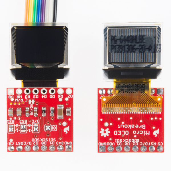
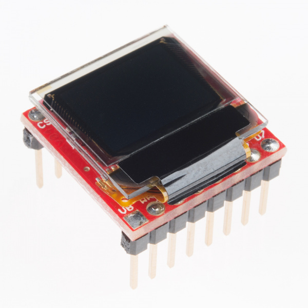
Also think about how you want the screen to be visible. The board is designed so you can either fold the display over, or have it flop off the edge of the board. The screen's orientation will determine which side of the board you'll need to solder to.
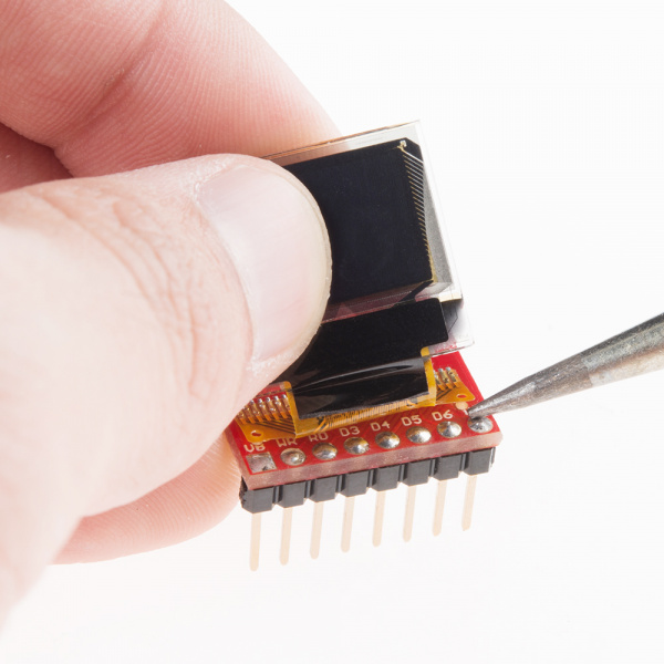
Even if you're not going to use the extra eight pins, try to solder headers to them if you can. This will help balance the display if you're plugging it into a breadboard. Just take care not to burn the screen's connector as you solder these pins -- you can gently pull it back while applying the solder.
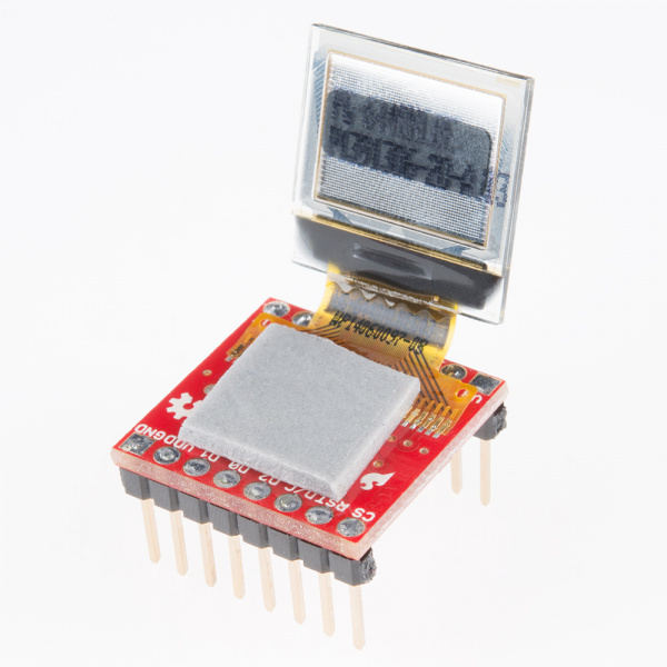
After soldering, you may want to secure the display with some tape -- especially if you're going with the "fold-over" method. Double-sided foam tape is perfect for this application.
Fold the display over and it should fit perfectly within the PCB's outline.
Setting Jumpers for I2C Mode
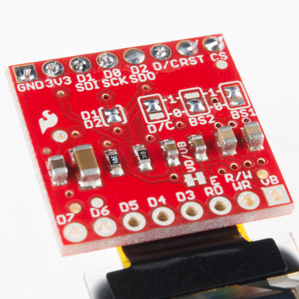
If you're controlling the display over I2C, you'll need to make a few modifications to the jumpers:
- Short D1/D2 -- This will combine the data output line and data input line into one.
- Set BS1 to 1 -- The BS1 jumpers comes defaulted to 0, which does half the job of setting it to SPI. To set the display to I2C, you'll need to flip that jumper to 1. Also make sure the BS2 jumper remains set to 0.
- Set D/C -- In I2C mode, the D/C pin configures the display's 7-bit address. You can set it to either 0 or 1, just keep that value in mind when you get to the code part of this tutorial.
Once you're done setting jumpers, the back of the board should look a little something like this:
