$20.95
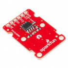
The MAX31855K Thermocouple Breakout is a simple 14-bit resolution, SPI-compatible, serial interface thermocouple digitizer that makes reading a wide range of temperatures possible. We've broken this device out on a breakout board along with all the necessary componets to make using it a breeze!
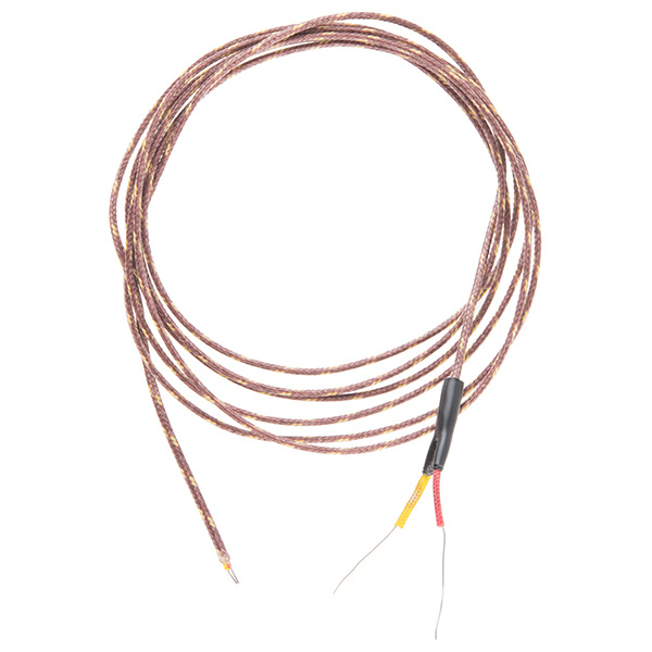
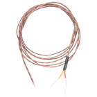
This breakout is designed to be used in conjunction with a k-type thermocouple such as this one shown below.
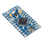
In this tutorial we're going to get you familiar with the workings of the MAX31855K. We'll go over how to hook it up to a our 3.3V Arduino Pro Mini, but you can use this breakout board with nearly limitless other options. Anything that can communicate over SPI will do. It can be as 'simple' as a custom set of logic gates, most micros, or as complicated as yours server's motherboard. Make sure you are using 3.3V, or level shifting into the range 3.0V to 3.6V. We'll close the tutorial out with some example Arduino code.
To follow along with this tutorial, you'll need the following:
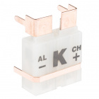
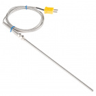
Alternatively, you may use this thermocouple probe in conjunction with the thermocouple connector
To connect the breakout to the microcontroller, you will likely want some male headers, or you could use a few pieces of wire.
Additionally, you may want the following:
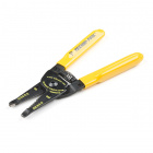
In order to get a good, solid, electrically-sound connection to the breakout boards, you'll need to solder to the pins. That means you'll need at least a basic soldering iron as well as solder. Check out our how to solder tutorial for help, if this is you first time soldering.
You will also need the following supplies, but very well might already have them, or something equivalent laying around:

These boards aren't too hard to use. If you've done anything with Arduino before, you'll be prepared to work with the MAX31855K. If you're not exactly sure what this "Arduino" thing is, or if you're not familiar with the topics below, consider reading their tutorials:
Roughly a couple hundred years ago, a man named Thomas Seebeck discovered the principal that thermocouples use. He noticed that if you take two wires made of dissimilar metals, connect them at the two ends, and make a temperature gradient between one end and the other, a voltage potential formed, and current flowed. One junction is held in the environment where the temperature of interest exists. This is known as the hot junction. The other junction is referred to as the cold junction.

There are many types of thermocouples, which mainly differ by the types of metals used in the two wires. The most common general purpose thermocouple is type K. They are made out of chromel and alumel. These two alloys produce a potential of approximately 41.276 µV/°C. The MAX31855K uses this linear approximation to calculate the temperature.
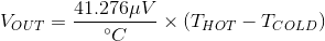
The thermocouple’s hot junction can be read from -200°C to +700°C with an accuracy of ±2°C. The cold junction is inside the MAX31855K and can only range from -20°C to +85°C while maintaining ±2°C accuracy. The MAX31855K constantly measures the temperature of the cold junction using an internal temperature-sensing diode. The internal 14-bit ADC uses the above equation, the voltage across the internal diode, and the amplified voltage of the thermocouple to solve for the hot junction temperature.
The calculated temperature is clocked out the SO pin in a SPI compatible format (half-duplex). When not feeding out data, this pin is tri-stated and will ignore any inputs from the master. A reading of 0b 0000 0000 0000 corresponds to 0°C. Whereas 0b 01 1001 0000 0000 corresponds to a measured temperature of +1600.00°C, and 0b 11 1100 0001 1000 corresponds to a measured temperature of -250.00°C.
Now, let's dive in and see how to connect the Thermocouple Breakout.
The first assembly step is creating a reliable, electrical connection from the breakout to your control board. You'll need to solder either headers or wires to your breakout boards, deciding if straight or right-angle headers or wire work best for you.
If you're going to stick the breakout board into a breadboard, other prototyping board, or an Arduino Pro Mini, straight male headers might be the best choice. You might want to solder some right angle headers to the short edge of the Pro Mini so it's easy to plugin the FTDI Basic.
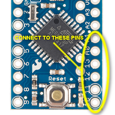
The MAX31855K requires from +3.0V to +3.6V (+3.0V nominal). Since the MAX31855K only draws 1.5 mA maximum, this tutorial will use D14 for power. This lets use line up all of the SPI and power pins on one compact row. One could also power the board from any similar power supply.
This hookup is fairly straightforward. We need so little power, we can connect the breakout to the sequential pins D10-A1. Since the MAX31855K is read-only, pin D11(MOSI) isn't connected on the breakout board & can be used for other functions such as SS for a second thermocouple board.Make your connections as follows:
| Thermocouple Breakout Pin | Arduino Pin | Function |
|---|---|---|
| GND | A1 | Ground |
| VCC | A0 | Digital pin set to 3.3V in |
| SCK | D13 | Clock |
| SO | D12 | Serial Data Out |
| NC | NC (D11) | No Connect (can float on D11 for easy hookup) |
| CS | D10 | Chip Select |
As covered in the previous section, potentials are formed due to a temperature gradient between junctions of dissimilar metals. We want to minimize the number of these junctions ideally down to two: the hot at the end of the thermocouple, and the cold at the MAX31855K. Every connection in addition to these can skew the reading. The breakout board is designed to accept a standard thermocouple connector, for convenience and compatibility with probes you may already own. These connectors aren't necessary, and you could solder a thermocouple directly into the through holes labeled '+' and '-'.
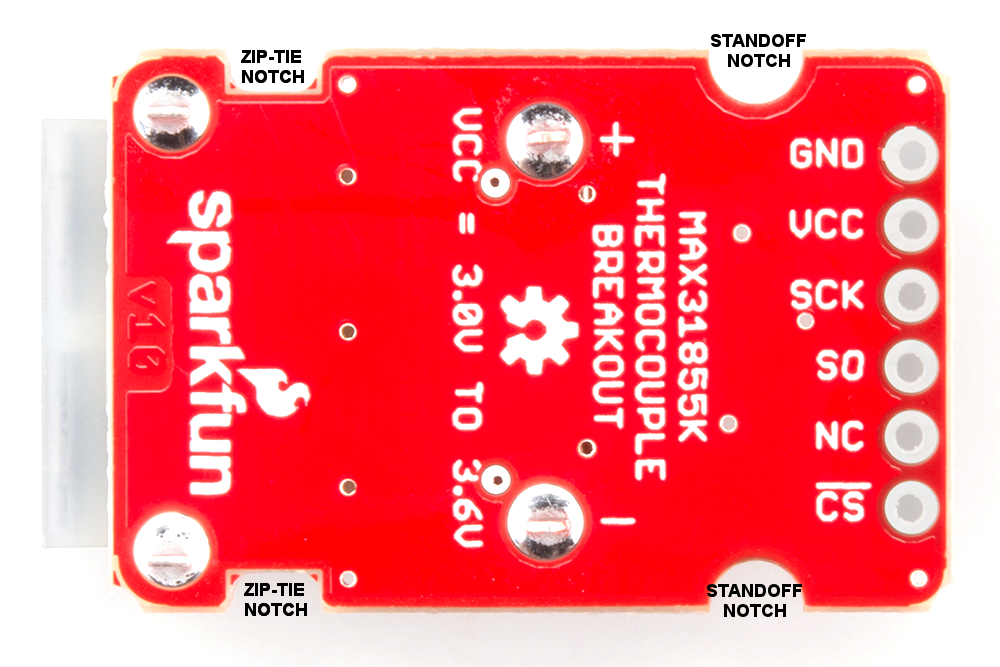
If you decide to solder the thermocouple directly to the breakout board, it is recommended that the thermocouple be mounted for strain relief to avoid breaking the thin wires. Notches have been provided in the PCB opposite the header for this purpose. One could wrap the thermocouple around this part of the board and squirt on some hot glue, or a zip-tie can be wrapped around the notches to hold the thermocouple. These zip-tie notches can also be used to attach the board to your project.

If you opted for the connector, your circuit will look more like this:
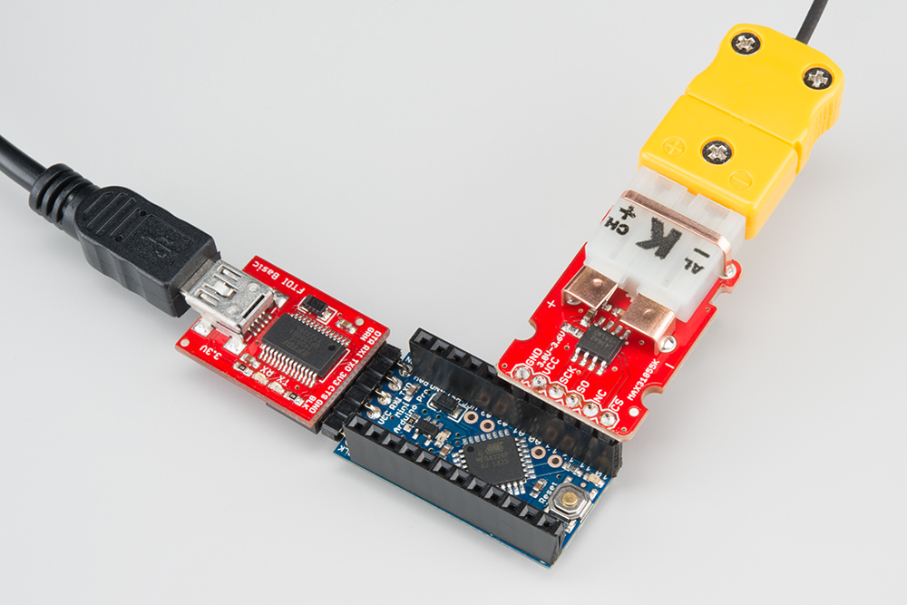
For ease of use in this particular application, I chose to solder female headers to all holes on the top of the Arduino. I also soldered a male header to the bottom of the breakout board.
There is no need to mount the breakout board, but we have provided several ways to make it easy. Hot-glue and double-sided foam tape work, as always. We also provided notches for zip-ties. Grab a zip-tie, loop it around the PCB and any object, and pull it tight. There are also notched out holes for our standard standoffs and screws. find or make two holes 20 mm apart, center-to-center, and screw the board down. These same notches can also be used for a zip-tie, some conductive thread, or let your imagination go wild!
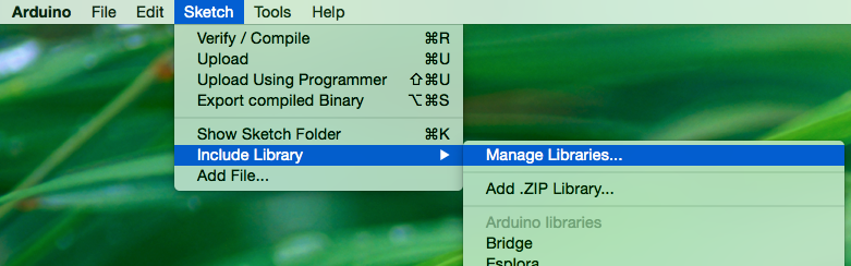
The library for this product is written to be compatible with Arduino IDE versions 1.5 and greater (1.6.x). The Arduino SPI library has changed in these versions, and our library relies on the more recent version. Since you are required to be running a recent version of the IDE we can use the handy new Library Manager feature. It is found in the 'Sketch' menu under 'Include Library', 'Manage Libraries...'
When you open the Library Manager you will find a large list of libraries ready for one-click install. To find the library for this product, search for 'k type' or 'digitizer', and the library you want will likely be the only option. Click on that library, and the 'Install' button will appear. Click that button, and the library should install automatically. When installation finishes, close the Library Manager.

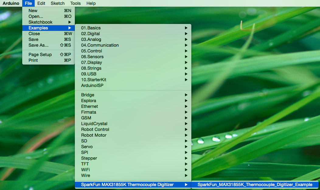
Now that the library is installed, an example sketch can be found in the 'Examples' submenu. Open this example.
language:cplusplus
/**************** MAX31855K_Thermocouple_Digitizer_Example.ino *****************
 *                                                                             *
 * MAX31855K Thermocouple Breakout Example Code                                *
 * brent@sparkfun.com                                                          *
 * March 26th 2015                                                             *
 * https://github.com/sparkfun/MAX31855K_Thermocouple_Digitizer                *
 *                                                                             *
 * Use the "serial monitor" window to read a temperature sensor.               *
 *                                                                             *
 * Circuit:                                                                    *
 * MAX31855K breakout attached to the following pins                           *
 *  SS:   pin 10                                                               *
 *  MOSI: pin 11 (NC)                                                          *
 *  MISO: pin 12                                                               *
 *  SCK:  pin 13                                                               *
 *  VCC:  pin 14                                                               *
 *  GND:  pin 15                                                               *
 *                                                                             *
 *                                                                             *
 * Development environment specifics:                                          *
 * 1.6.4                                                                       *
 * Arduino Pro Mini 328 3.3V/8MHz                                              *
 *                                                                             *
 * This code is beerware; if you see me (or any other SparkFun employee) at    *
 * the local, and you've found our code helpful, please buy us a round!        *
 * Distributed as-is; no warranty is given.                                    *
 ******************************************************************************/

#include <SparkFunMAX31855k.h> // Using the max31855k driver
#include <SPI.h>  // Included here too due Arduino IDE; Used in above header

// Define SPI Arduino pin numbers (Arduino Pro Mini)
const uint8_t CHIP_SELECT_PIN = 10; // Using standard CS line (SS)
// SCK & MISO are defined by Arduiino
const uint8_t VCC = 14; // Powering board straight from Arduino Pro Mini
const uint8_t GND = 15;

// Instantiate an instance of the SparkFunMAX31855k class
SparkFunMAX31855k probe(CHIP_SELECT_PIN, VCC, GND);

void setup() {
  Serial.begin(9600);
  Serial.println("\nBeginning...");
  delay(50);  // Let IC stabilize or first readings will be garbage
}

void loop() {
  float temperature = probe.readCJT();

  // Read methods return NAN if they don't have a valid value to return.
  // The following conditionals only print the value if it's not NAN.
  if (!isnan(temperature)) {
    Serial.print("CJT is (˚C): ");
    Serial.println(temperature);
  }

  // Read the temperature in Celsius
  temperature = probe.readTempC();
  if (!isnan(temperature)) {
    Serial.print("Temp[C]=");
    Serial.print(temperature);
  }

  // Read the temperature in Fahrenheit
  temperature = probe.readTempF();
  if (!isnan(temperature)) {
    Serial.print("\tTemp[F]=");
    Serial.print(temperature);
  }

  // Read the temperature in Kelvin
  temperature = probe.readTempK();
  if (!isnan(temperature)) {
    Serial.print("\tTemp[K]=");
    Serial.print(temperature);
  }

  // Read the temperature in Rankine
  temperature = probe.readTempR();
  if (!isnan(temperature)) {
    Serial.print("\tTemp[R]=");
    Serial.println(temperature);
  }

  delay(750);
}
language:cplusplus
// Define SPI Arduino pin numbers (Arduino Pro Mini)
const uint8_t CHIP_SELECT_PIN = 10; // Using standard CS line (SS)
// SCK & MISO are defined by Arduiino
const uint8_t VCC = 14; // Powering board straight from Arduino Pro Mini
const uint8_t GND = 15;
This block of code, found above the setup function in the main sketch, is where you will configure the pins used to communicate with the MAX31855K breakout. If you are using another board, or another power supply, you will want to edit these!
Serial.begin(9600);
Before using the serial monitor, you must call Serial.begin() to initialize it. 9600 is the "baud rate", or communications speed. When two devices are communicating with each other, both must be set to the same speed.
float temperature = probe.readCJT();
All of the temperature reading functions return floating point values. Floating point numbers are any number that isn't a whole integer number. '1' is and integer, while '1.01' is a floating point number. One special floating point number is NaN, or Not a Number. It represents things that aren't real numbers such as 0/0 (divide by zero is 'undefined'). If a temperature reading function returns NAN it means that a real temperature wasn't read, and it's time to check your hardware.
At this point the hardware should be correctly connected, the library should be installed, and the example sketch should be opened. Select the correct serial port in the 'Port' submenu of the 'Tools' menu. Click the 'Upload' button, or sleect 'Upload' in the 'Sketch' menu. The code should compile and be uploaded to the Arduino. Once the code upload finishes verifying, open the serial monitor (found in the 'Tools' menu).
You should be able to read the temperature your thermocouple is detecting on the serial monitor in the Arduino IDE. If it isn't working, make sure you have assembled the circuit correctly and verified and uploaded the code to your board.
Example of what you should see in the Arduino IDE’s serial monitor:
language:cplusplus
Beginning...
CJT is (˚C): 25.94
Temp[C]=26.50   Temp[F]=79.70   Temp[K]=299.65  Temp[R]=539.37
...
...
...
Beginning... only prints once to mark the beginning of the code running. The next two lines show the Cold Junction Temperature (CJT), followed by the thermocouple measurement in a handful of common units. The CJT is the temperature of the breakout board, and the other temperature reading is that of the tip of your thermocouple. These two lines of temperature readings should be updated and reprinted every 3/4 of a second.
This program has no outward indication it is working. To see the results, you must open the Arduino IDE's serial monitor.
This happens because the serial monitor is receiving data at a different speed than expected. To fix this, click the pull-down box that reads "*** baud" and change it to "9600 baud".
Try pinching the sensor with your fingers to heat it up or pressing a bag of ice against it to cool it down. Boiling water should be about 100°C, while ice should be about 0°C.
Thanks for reading. Here are some resources you may find handy:
Check out these other great tutorials from SparkFun.
learn.sparkfun.com | CC BY-SA 3.0 | SparkFun Electronics | Niwot, Colorado