Magnetic Levitation
 Alex the Giant
Wireless Power
If levitating a magnet isn't cool enough, you can add even more complexity by adding a wirelessly powered LED. This step requires a few more tools that not everyone has. For this section you'll need the following:
Building the transmission coil
The inductor used to levitate the magnets only provides enough power to keep the magnet in position. To transfer power wirelessly, we'll need to make a second inductor that we'll wind ourselves using magnet wire. Magnet wire is thin gauge wire with an even thinner insulating layer. This allows the coils of the wires to get even closer together and increases the inductance created as compared to the same number of turns of normally insulated wire.
Wireless power transfer works on the same principal as a transformer, where you have one inductor induce a current on another inductor, except instead of using an iron core to couple the flux from one inductor to another, it uses air, similar to a tesla coil. One of the problems with wireless power transfer is that it's very inefficient. The primary side of the transformer will use a lot of power to generate a little bit of power on the secondary.
Making The Primary
The primary is made with 25 turns of 30 gauge magnet wire with a center diameter of 1 inch. Because engineers are incapable of throwing anything away, I used an empty hookup wire spool with one end cut off to slide off the magnet wire.
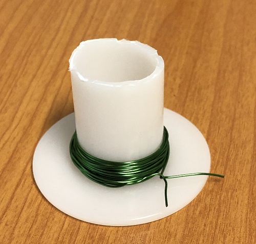
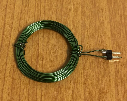
To keep the coil from unwinding, you can cut off a small piece of extra magnet wire and wrap it around the primary on two of the sides so that it will hold its shape. The enamel coating on the wire makes it hard for solder to stick to the wire. So with a little bit of sand paper, file off some of the enamel so that you can solder on a couple of pins as shown below, or solder wire directly to the coil to reach the breadboard.
Making The Secondary
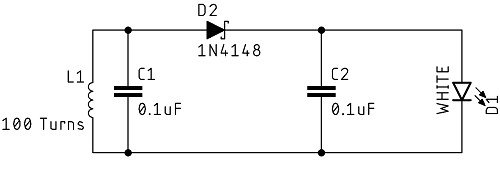
The secondary side was made in the same way, except using 100 turns of magnet wire this time, along with a diode and two capacitors to convert the AC power to DC power for the LED. Refer to the schematic below.
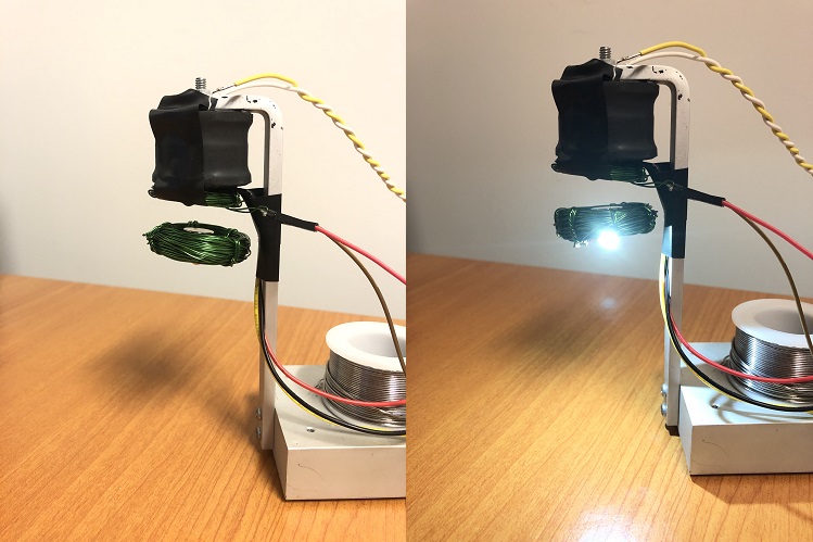
Cut off some extra pieces of magnet wire to hold the secondary together as was done with the primary. Cut off larger pieces this time to loop around the heatsink of the LED to hold in the center of the secondary. A piece of double sided tape was used to hold the magnets to the bottom of the LED heatsink. Make sure when positioning the magnets that the mark on the magnets is facing away from the LED.
 |
 |
| Assembled Secondary - Top | Assembled Secondary - Bottom |
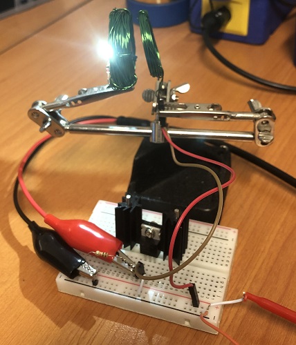
Building the Primary Driver and Testing
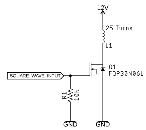
In order to induce a current across the secondary coil, we need to generate an AC signal using a function or frequency generator that will allow us to find the best frequency to use with these inductors we made. Just like with the op-amp for the levitation circuitry, the function generator cannot source very much current, so we'll need to use another mosfet to drive our primary coil. The circuit is pretty simple, with the square wave input signal having an amplitude of 5V, and a DC offset of 2.5V (what we want is a square wave which goes high to 5V and low to 0V). Make sure to attach a heatsink to this mosfet, as they get pretty hot, pretty quickly.
To find the best frequency to use, I used my LCR meter, which can measure the inductance of my secondary coil, along with getting an accurate value for the C1 from the schematic, and calculated the resonant frequency to be around 80kHz. There's a balance between the frequency and current draw from the power supply. The lower the frequency, the brighter the LED will be, but the efficiency is extremely low and the mosfet driving the primary coil will get extremely hot. The best approach to this problem is to determine how high of a frequency can you use and still have sufficient LED brightness.
Attaching the Primary to the Levitating Inductor
Now that the wireless power transfer is working, it's time to attach the wireless power primary inductor to the levitation inductor. With a little bit of electrical tape, attach the 25 turn inductor we made on the bottom of levitation inductor where the hall effect sensor is.

Finding the New Levitation Distance
The weight of the light and magnets is now significantly heavier than with the magnets alone. With the wireless power primary disconnected from the rest of the circuit, use the reference voltage potentiometer to adjust the levitation distance. Because of the mass, the magnets will need to be significantly closer, around 1cm. Turning the voltage down on the potentiometer will decrease the levitation distance. Once you have the light levitating, you can reconnect the primary and turn the output of the function generator on and off to control the LED.
I mentioned earlier that this was inefficient. Just how inefficient though? I measured the current to be around 50mA, and the voltage across the LED was 2.72V, so the circuit is receiving around 136mW of power. The power supply is set to 12V, and with the magnet levitating and the light on, the circuit is drawing 886mA, or 10.6 watts, which makes the efficiency 1.3%. To be fair though, the levitation circuit is drawing about 450mA, so the wireless power transfer efficiency is really about 2.5%. Now that we know what frequency our wireless power circuit can run at, the function generator could be replaced with a new circuit using a 555 timer to generate the square wave signal.