Magnetic Levitation
 Alex the Giant
Building The Control Circuit
As mentioned in the Theory Basics, it's important that the magnet is positioned close enough to the inductor's magnetic field that it is able to interact with the magnet, but not so close that the magnet's own magnetic field is able to pull itself up to the inductor regardless of the power. What we need is a way to control the inductor so that when the magnet is too far away, the inductor will pull the magnet closer, but turn off when it gets too close, so that gravity can still pull it back down.
Before we start wiring up electronics, a stand has to be made to hold the inductor above the ground. This guide isn't going to go over making a stand, but below is a photo of the stand used for reference. The inductor hangs about 5 inches above the table, and a 8-32 bolt (~1.5 inches in length) and nut are used to attach the inductor to the stand.
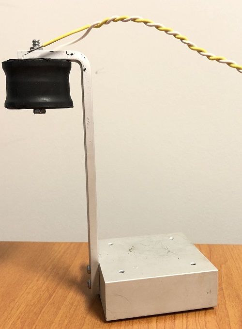
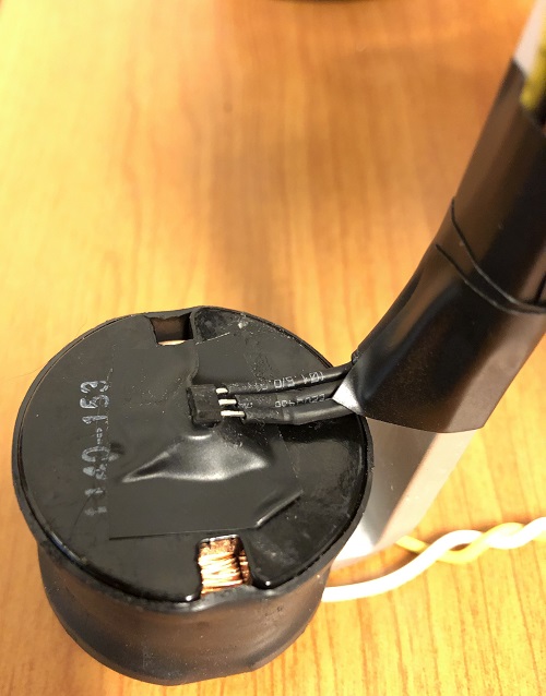
Once the inductor is mounted, we'll need to attach the hall effect sensor to the head of the bolt. If there's any exposed metal from the sensor, use a piece of electrical tape to insulate the sensor from the bolt and secure the sensor with more electrical tape as shown below. Note that the curved side of the sensor is facing away from the inductor.
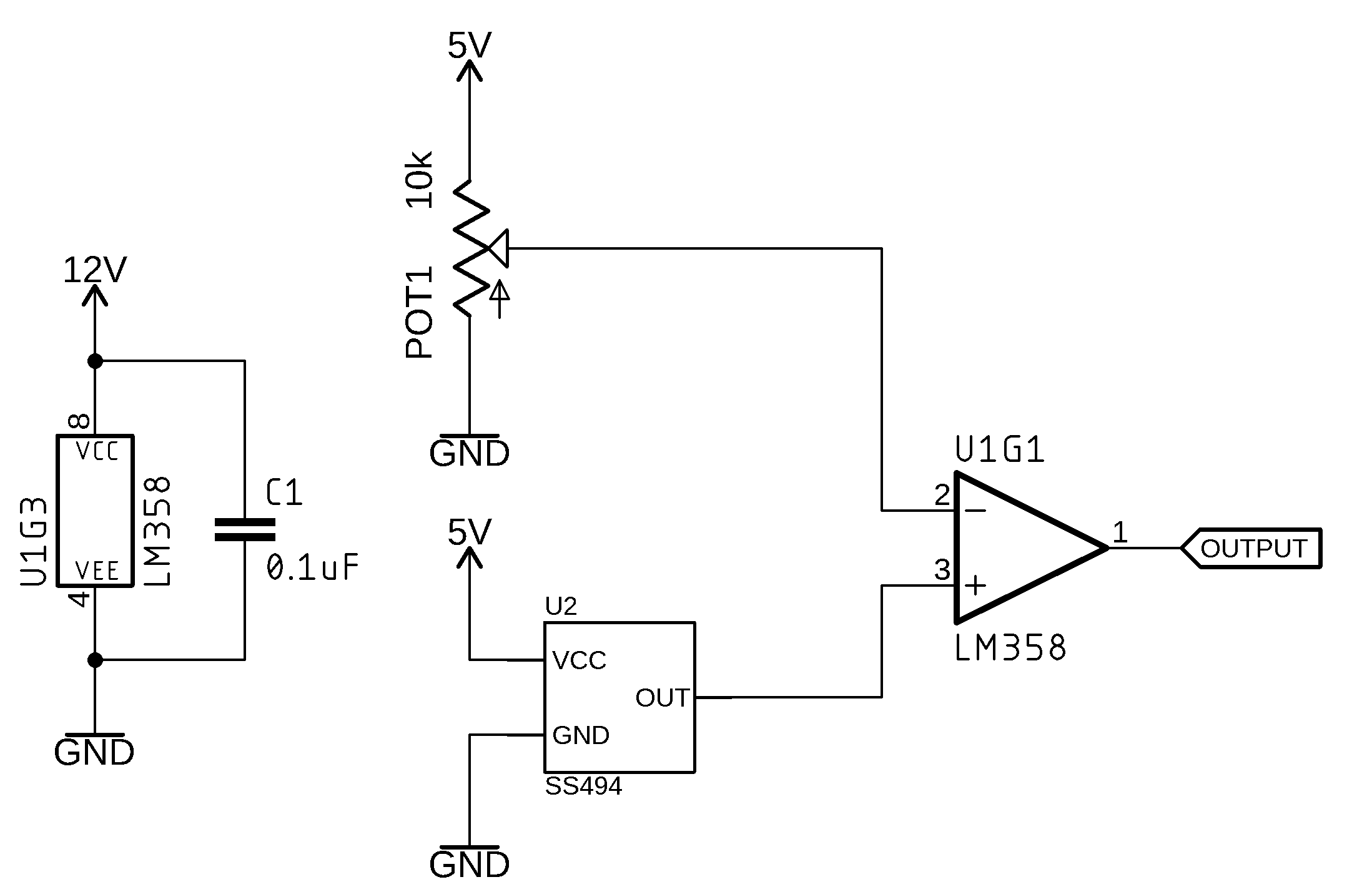
The Comparator Circuit
To control the inductor we're going to use an op-amp in a configuration called a comparator, which compares the output of the hall effect sensor to a reference voltage that is connected to the other input pin. The reference voltage is set with a potentiometer acting as a voltage divider - this creates an adjustable analog voltage between 0V and 5V. The voltage of the potentiometer represents what voltage we want the hall effect sensor to read, which is based on how far away the magnet is.
This circuit uses two voltage rails, 5V and 12V. The 12V rail is powering the inductor and op-amp, and the 5V rail is used for the voltage reference and hall effect sensor. Two power supplies are ideal, because if the 12V rail goes into current limiting mode, and the voltage drops, the hall effect sensor won't have a high enough voltage to detect when the magnet is close enough. You can, however, get away with a single power supply rail using a LM7805 linear voltage regulator. If you plan on using two power supplies, make sure you connect the grounds together, otherwise the circuit won't work correctly.
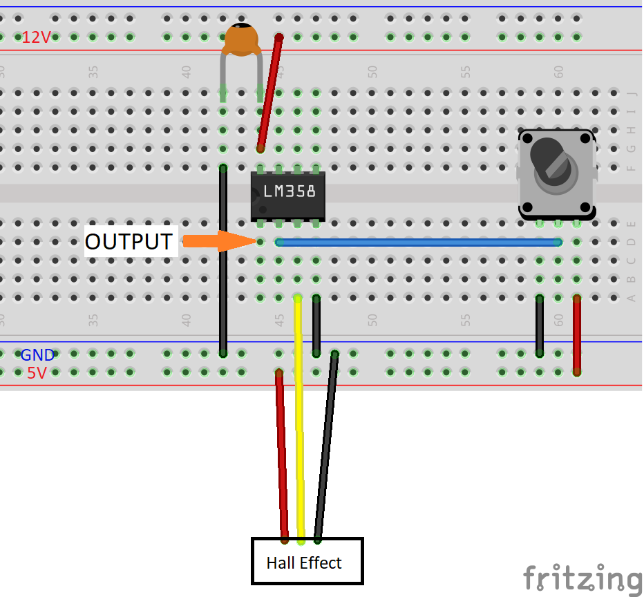
Once the circuit is built, we'll use a multimeter to measure the voltage at the non-inverting input (pin 2 of the op-amp) and turn the knob on the potentiometer until it reads 0V. Next, we'll position the magnet about 2cm away from the sensor, or about a thumb's thickness. Essentially, the magnet needs to be in the "sweet spot" - a position a bit further away than the position where the magnet wants to pull up on its own and stick to the inductor.
Looking at the output voltage of the op-amp (pin 1), it should be reading 9-12V. With the magnet still in position, we're going to slowly turn the potentiometer and increase the reference voltage until we see the voltage change from 12V to 0V. Moving the magnet up and down a little should change the output of the op-amp from high to low and low to high.
The comparator is trying to keep the voltages between the input pins equal and driving the output high or low so that the sensor value matches the reference value. In the next step we'll attach our inductor to the output of the op-amp and try to make a magnet levitate!