LuMini Ring Hookup Guide
Hardware Overview
I/O Pins
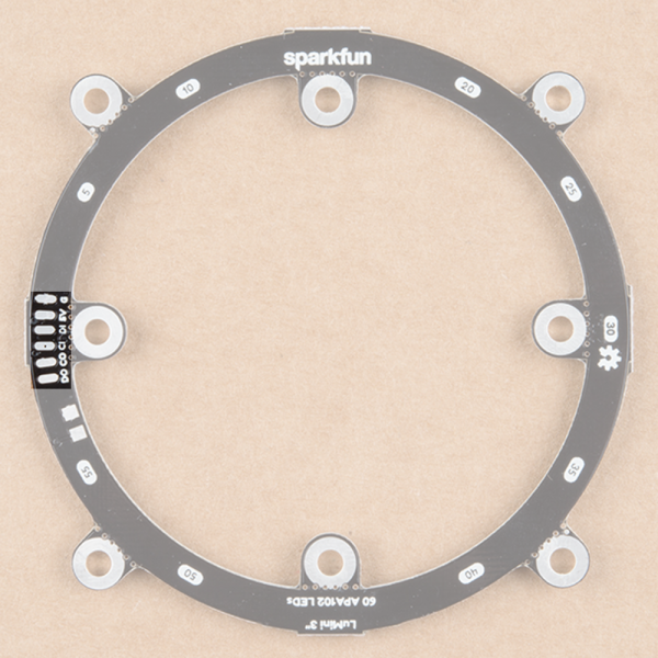
The LuMini rings are powered and controlled using a few pads on the back of each board. Each board has a set of pads for 5V and ground, a set of pads for data and clock input, and a set of pads for data and clock output. These pads are outlined in the below image.
Decoupling Capacitor Pads
In larger installations you may need to add a decoupling capacitor between power and ground to prevent voltage dips when turning on a whole bunch of LED's simultaneously. The spot to add this optional capacitor is outlined below.
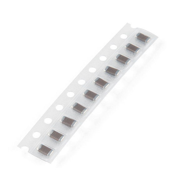
We'd recommend the surface mount 4.7 µF capacitor that is shown below. If you've never done surface mount soldering before, this part might be a little tricky, but check out our SMD tips and tricks on doing just that.
Capacitor 4.7uF - SMD (Strip of 10)
COM-15169LED Numbers
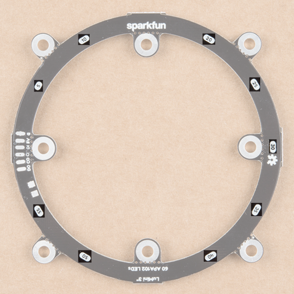
Looking at the back of each ring, you'll also see some numbers. Since the ring acts like a string of LEDs, these numbers correspond to the LED number in the string. Note that, like the led array, we index at LED 0, so calling leds[5] will correspond to the LED on the opposite side of the 5 labeling.
32 is good for testing, as it's a little easier on the eyes. However, turning the brightness up all the way and leaving all LED's on white will result in damage to your ring! Be careful to make sure your animations don't run too hot, and if they do, you can always lower the brightness.


