LuMini 8x8 Matrix Hookup Guide
Hardware Overview
I/O Pads
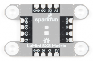
The LuMini Matrix is powered and controlled using a few pads on the back of each board. Each board has a set of pads for 5V and GND (ground), a set of pads for DI (data in) and CI (clock input), and a set of pads for DO (data out) and CO (clock output). These pads are outlined in the below image.
APA102
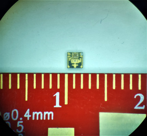
The APA102 is an addressable RGB LED with 8-bit color (256 colors) and 256 levels of gray scale. This essentially means that you can tell each individual LED what color you want it to show and how bright it should be.
The LEDs employ a 2-wire communication protocol consisting of a clock line and a data line. While this requires one more wire than standard WS2812B addressable LEDs, the advantage is that the communication with the LEDs becomes somewhat timing independent, allowing you to run these off boards without long, precisely-timed data streams.
32 is good for testing, as it's easier on the eyes. You can also tape a small piece of paper to the front to get better diffusion of each LED.
LED Indexing
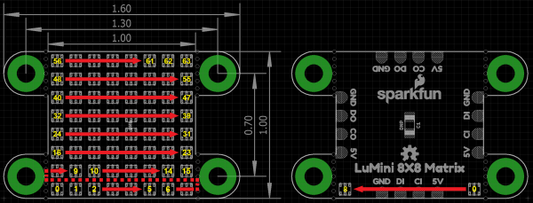
Each matix acts like a string of LEDs. The indexing (or numbering) of the LEDs moves from left to right, bottom to top of the board, on the LED facing side, as shown in the diagram below.
Capacitor Pads
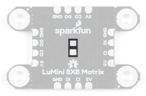
In larger installations you may need to add a decoupling capacitor between power and ground to prevent voltage dips when turning on a whole bunch of LEDs simultaneously. The spot to add this optional capacitor is outlined below.
We'd recommend the below 4.7 µF capacitor. If you've never done surface mount soldering before, this part might be a little tricky, but check out our SMD tips and tricks on doing just that.
Heat Dissipation
As with most high power LEDs, the APA102 LEDs used on the LuMini Matrix 8x8 generate a lot of heat. To keep the LEDs from damaging themselves and the board, the ground plane (back/bottom layer of the board) is used for heat dissipation. The stand off pads are also tied to the ground plane and can be used for greater thermal dissipation.
We've found that setting the global brightness using the FastLED Library to
32 is good for testing, as it's easier on the eyes. Even if all the LEDs are set to white, the temperature of the board will idle around (90-95°F... depending on your ambient room temperature).

Setting all the LEDs on white and turning the brightness up all the way up will result in damage to your board and may result in injury and/or fire ! We only ran our display for about 20-30 seconds before we decided to turn it off, in that time it climbed to over 300°F and was still rising!
