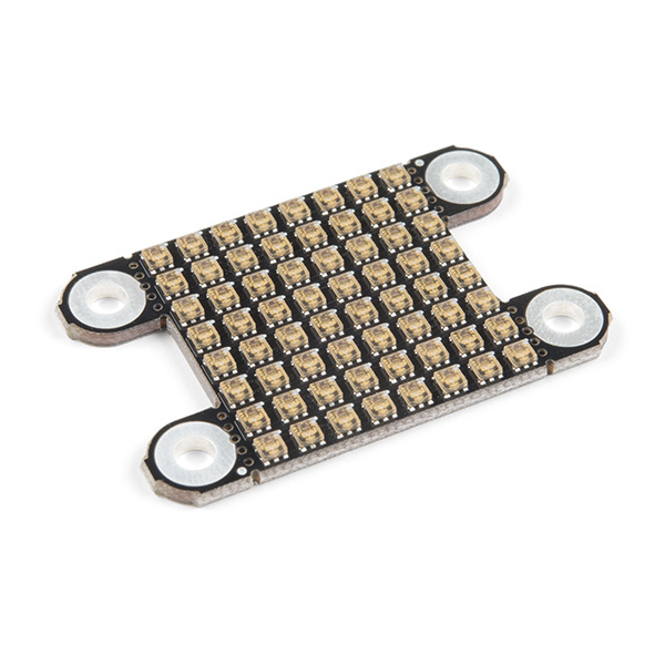
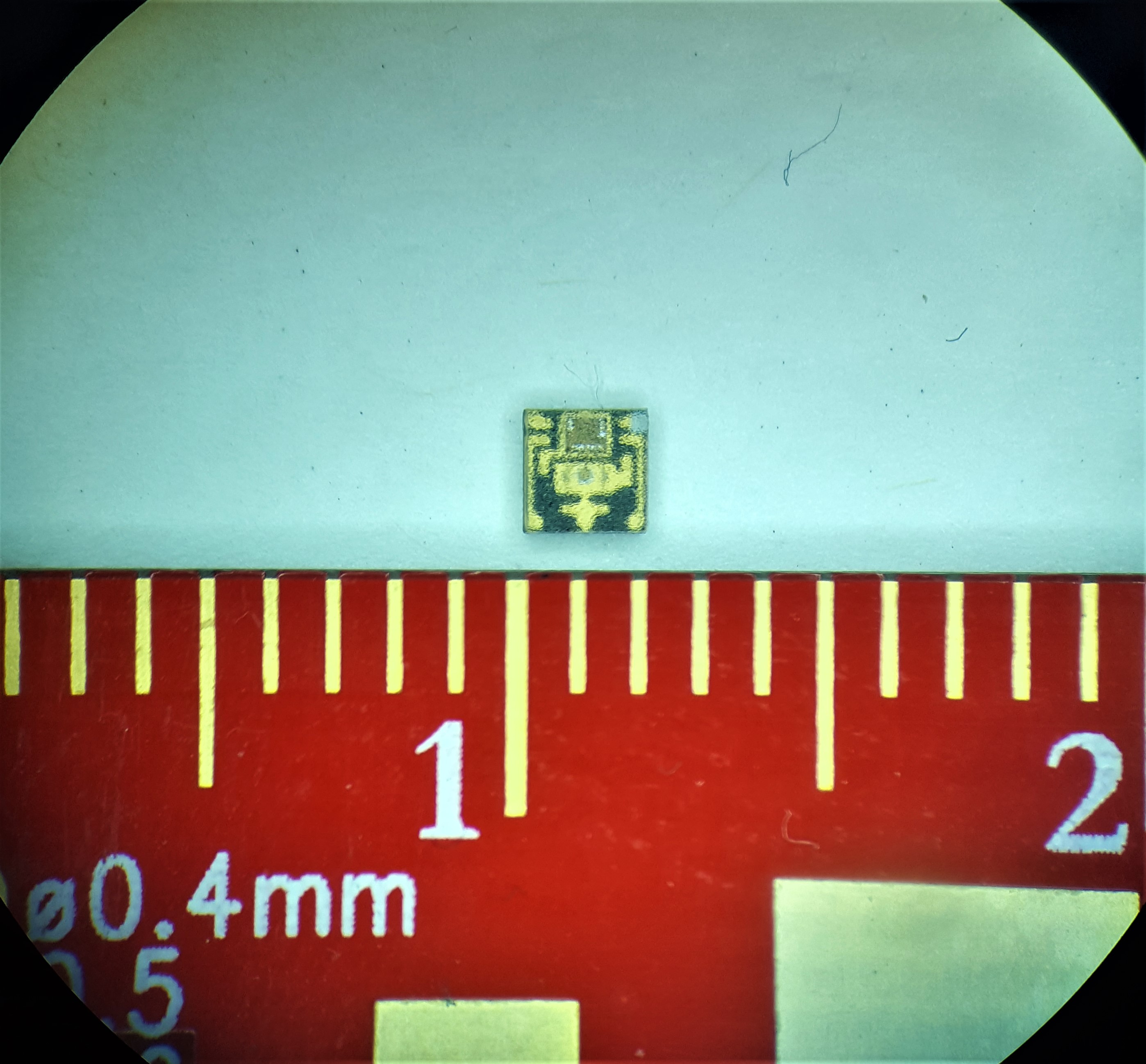
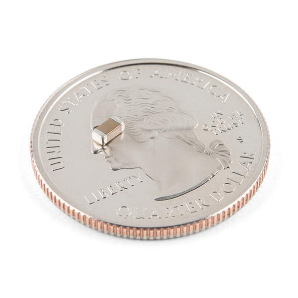
The LuMini 8x8 Matrix is a great way to add a square of light to just about anything, or even make a screen of a custom shape. The LuMini product line uses the same LED used on our Lumenati boards, the APA102, just in a smaller, 2.0x2.0 mm package. This allows for incredibly tight pixel densities, and thus, a screen with less pixelation. The LuMini Matrix packs 64 LEDs into a measly square inch!
In this tutorial, we'll go over how to connect the LuMini Matrix up to more LuMini Matrices as well as other APA102 based products. We'll check out how to map out a matrix of lights in software so we can get a little more creative with our animations. We'll go over some things to consider as you string more and more lights together, and we'll also go over some neat lighting patterns to get you away from that standard rainbow pattern (Iif you have 16 million colors why would you use 255).
To follow along with this tutorial, you will need the following materials. You may not need everything though depending on what you have. Add it to your cart, read through the guide, and adjust the cart as necessary.
You'll need a microcontroller to control everything, however, there are a few things to consider when picking out one to control a whole ton of LEDs. The first thing is that, although they don't have to operate at a specific timing, APA102 LEDs can transmit data really really fast for an LED, 20 MHz fast! So you should use a microcontroller that is fast enough to take advantage of this capability. Another consideration is the amount of RAM taken up by the LED frame; especially, when you start getting into higher LED counts. Each LED takes up 3 bytes of space in RAM. This doesn't sound like a lot, but if you're controlling 5000 LEDs, you might need something with a bit more RAM than your traditional RedBoard. The below chart outlines the amount of LED's where you may start running into memory issues. Keep in mind that these are very generous estimates and will decrease depending on what other global variables are declared.
| Microcontroller | Max LED's | Clock Speed |
|---|---|---|
| SparkFun RedBoard | 600 | 16 MHz |
| Arduino Mega 2560 | 2600 | 16 MHz |
| Pro Micro | 700 | 16 MHz |
| SparkFun ESP8266 Thing | 27,000 | 160 MHz |
| SparkFun ESP32 Thing (Plus) | 97,000 | 160 MHz or 240 MHz |
| Teensy 3.6 | 87,000 | 180 MHz (240 MHz Overclock) |
It's pretty easy to choose either the ESP32 or Teensy 3.6 when it comes to stuff like this, as they've got a ton of overhead in clock cycles to run wacky calculations for animations. However, if your project isn't all about lights, and you're just tossing a LuMini Ring on a project as an indicator, less powerful microcontrollers will suffice.
Here are links to the ESP32 Thing, ESP32 Thing Plus, and Teensy 3.6; otherwise, you can look at the other microcontrollers listed in our catalog:
If you want headers for these boards, here are links to those products.(*The Teensy 3.6 has 24 breadboard pins, so you can use 4 of the photon headers. The ESP32 Thing Plus has a Feather form factor, so you will want to use headers that are sized accordingly or use the feather stackable header kit.)
In most cases, your LED installation is gonna pull more current than your board can handle. Depending on the brightness and animation, anywhere from 100-250 LED's will be too much for your board's voltage regulator, so you should snag a sweet 5V power supply that's got enough wattage in the cottage for all of your LED's. Here are a few 5V power supplies to start off with:
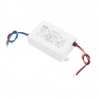
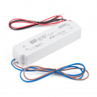
You can either estimate the necessary size of your power supply by taking the amount of LED's and multiplying by 60 mA (0.06 A) which is the amount of current it takes to run an LED at full white. This calculation will give you the maximum amount of power your LED's could draw. However, most of the time, this is a gross overestimate of the amount of power you'll actually end up consuming. Instead of calculating the maximum current draw, I usually like to test my completed installation on a benchtop power supply using the brightest animation it'll be running, and then add 20 or 30 percent to give myself a little wiggle room if I want to turn the brightness up in the future.
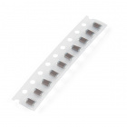
You will also probably need some soldering equipment and a 4.7 µF SMD capacitor (in a 603 package). The capacitor will be used to decouple the power supply. This will reduce high frequency noise in the power line and compensate for voltage drops due to the change in current demand from devices turning on and off. The 603 package might be a little tricky to solder, a good set of tweezers will help.

If you aren’t familiar with the following concepts, we recommend checking out these tutorials before continuing.
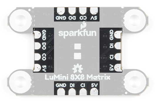
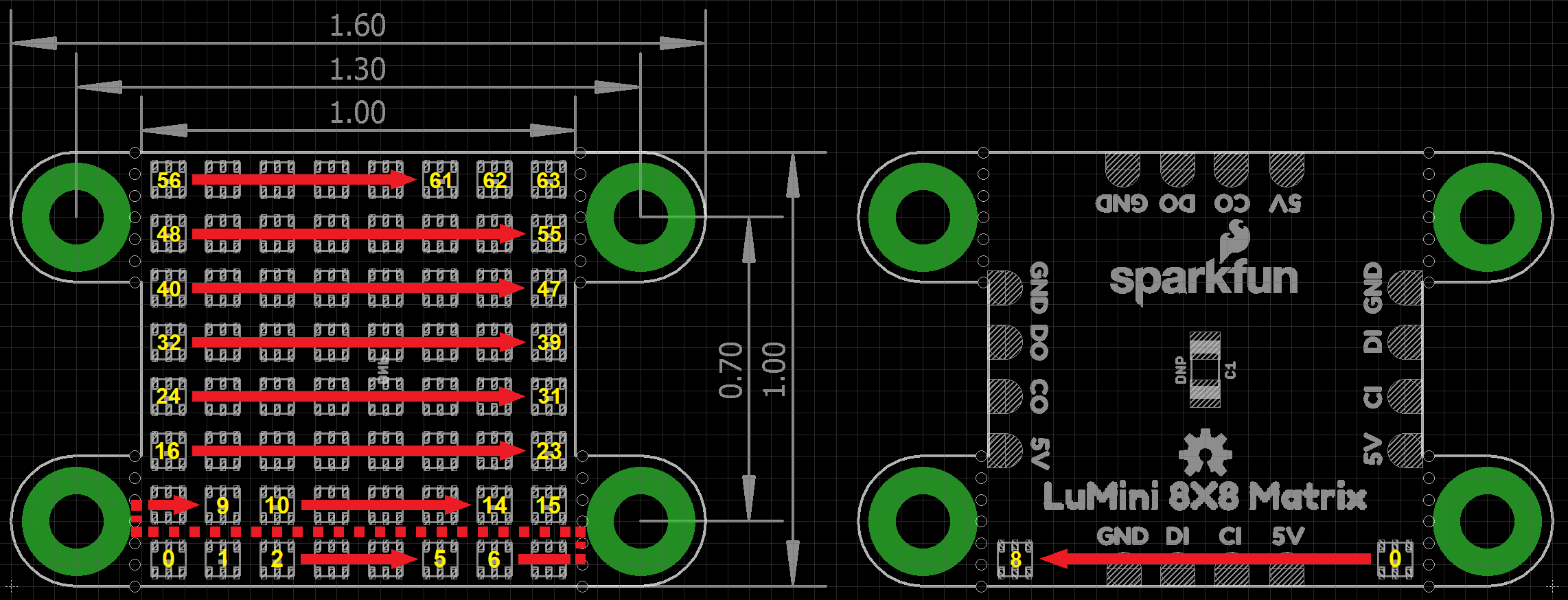
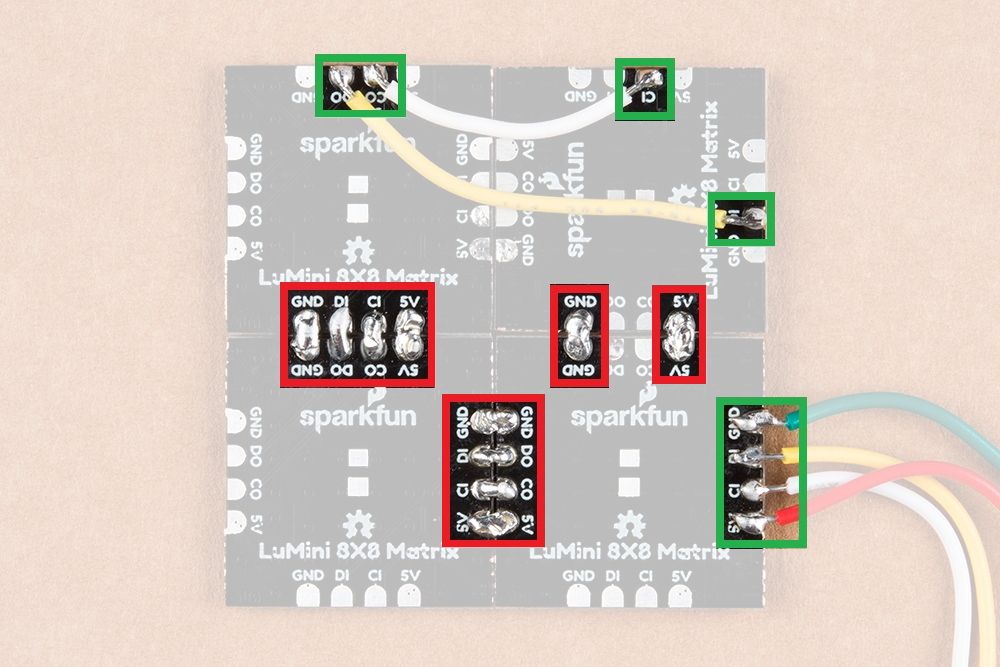
The LuMini Matrix is powered and controlled using a few pads on the back of each board. Each board has a set of pads for 5V and GND (ground), a set of pads for DI (data in) and CI (clock input), and a set of pads for DO (data out) and CO (clock output). These pads are outlined in the below image.
The APA102 is an addressable RGB LED with 8-bit color (256 colors) and 256 levels of gray scale. This essentially means that you can tell each individual LED what color you want it to show and how bright it should be.
The LEDs employ a 2-wire communication protocol consisting of a clock line and a data line. While this requires one more wire than standard WS2812B addressable LEDs, the advantage is that the communication with the LEDs becomes somewhat timing independent, allowing you to run these off boards without long, precisely-timed data streams.
32 is good for testing, as it's easier on the eyes. You can also tape a small piece of paper to the front to get better diffusion of each LED.
Each matix acts like a string of LEDs. The indexing (or numbering) of the LEDs moves from left to right, bottom to top of the board, on the LED facing side, as shown in the diagram below.
In larger installations you may need to add a decoupling capacitor between power and ground to prevent voltage dips when turning on a whole bunch of LEDs simultaneously. The spot to add this optional capacitor is outlined below.
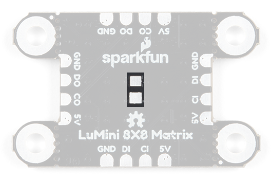
We'd recommend the below 4.7 µF capacitor. If you've never done surface mount soldering before, this part might be a little tricky, but check out our SMD tips and tricks on doing just that.
As with most high power LEDs, the APA102 LEDs used on the LuMini Matrix 8x8 generate a lot of heat. To keep the LEDs from damaging themselves and the board, the ground plane (back/bottom layer of the board) is used for heat dissipation. The stand off pads are also tied to the ground plane and can be used for greater thermal dissipation.
32 is good for testing, as it's easier on the eyes. Even if all the LEDs are set to white, the temperature of the board will idle around (90-95°F... depending on your ambient room temperature).

Soldering wires to the pads on the LuMini Matirx is pretty simple. The trick is simply to pre-solder both the pad and wire before attempting to solder the two together. Then, press the wire onto the pad and solder away! Check out the below GIF if you're a little confused.
The APA102 LED is controlled on an SPI-like protocol, so it's generally good practice to connect CI on the LuMini Matrix to SCLK on your microcontroller, and connect DI to MOSI. However, This setup isn't required, and you can connect data and clock up to most pins on your microcontroller. Go ahead and determine which pins you will use, and solder your Data and Clock lines into your microcontroller.

Now that we know how to solder to these pads, we can start making a grid of LuMini Matrices, or even tie them to other APA102 based products. To do this, all we'll need to do is solder CO and DO of one matrix panel to the CI and DI of the next matrix panel. Below, is an image multiple matrices soldered together to make a larger display.
Troubleshooting Tip: The standoffs mounting points can be clipped with a pair of dikes (diagonal wire cutters). You may need sand or file the edges square, since the diagonal cutters will leave a rough edge.
Note: This example assumes you are using the latest version of the Arduino IDE on your desktop. If this is your first time using Arduino, please review our tutorial on installing the Arduino IDE. If you have not previously installed an Arduino library, please check out our installation guide.
We'll be leveraging the ever popular FastLED library to control our LuMini Matrix. So go ahead and start by downloading the library by clicking the button below or searching for FastLED in the Arduino Library manager.
SparkFun has also written some example code specific to the rings to get you started. These example sketches can be found in the LuMini 8x8 GitHub Repo under Firmware. To download, click on the button below.
Make sure to adjust the pin definition depending on how you connected the LEDs to your microcontroller.
LEDS.setBrightness(##); (see Warning below).
Glen Larson invented the Larson Scanner as an LED effect for the TV series Knight Rider. In this example, we'll begin to reproduce it that effect and add in some color for flavor. This sketch is a great way to test all of the LEDs. First, we begin by creating an object for matrix CRGB matrix[NUM_LEDS].
language:c
#include <FastLED.h>

// How many leds in your chain? Change the value of NUM_BOARDS depending on your setup
#define NUM_BOARDS 1
#define NUM_LEDS 64 * NUM_BOARDS //64 LED's per board

// The LuMini matrices need two data pins connected, these two pins are common on many microcontrollers, but can be changed according to your setup
#define DATA_PIN 16
#define CLOCK_PIN 17

// Define the array of leds
CRGB matrix[NUM_LEDS];
We then, initialize the matrix using the LEDS.addLeds function below. Notice the BGR in this statement, this is the color order, sometimes, the manufacturer will change the order in which the received data is put into the PWM registers, so you'll have to change your color order to match. The particular chipset we're using is BGR, but this could change in the future.
language:c
void setup() {
  Serial.begin(115200);
  Serial.println("resetting");
  LEDS.addLeds<APA102, DATA_PIN, CLOCK_PIN, BGR>(matrix, NUM_LEDS);
  LEDS.setBrightness(32);
}
In this sketch, the global brightness is set to 32 LEDS.setBrightness(32);. Although, the full range of this setting is 0 to 255, we've found that 32 is good for testing, as it's easier on the eyes. Even if all the LEDs are set to white, the temperature of the board will idle around (90-95°F... depending on your ambient room temperature).
Our animation is then contained in the fadeAll() function, which loops through every LED and fades it to a percentage of it's previous brightness. Our loop() then set's an LED to a hue, we increment the hue, then show our LEDs. After this we use the fadeAll() function to fade our LED's down so they don't all end up being on.
language:c
void fadeAll() {
  for (int i = 0; i < NUM_LEDS; i++)
  {
    matrix[i].nscale8(250);
  }
}

void loop() {
  static uint8_t hue = 0;
  //Rotate around the circle
  for (int i = 0; i < NUM_LEDS; i++) {
    // Set the i'th led to the current hue
    matrix[i] = CHSV(hue++, 150, 255); //display the current hue, then increment it.
    // Show the leds
    FastLED.show();
    fadeAll();//Reduce the brightness of all LEDs so our LED's fade off with every frame.
    // Wait a little bit before we loop around and do it again
    delay(5);
  }
}
Your code should look like the below gif if you've hooked everything up right. If thing's aren't quite what you'd expect, double check your wiring.
As a challenge, see if you can create an actual Larson scanner. It should only take a few modifications to the example code.
In this second example, we'll use the serial terminal to control the color displayed by the matrix. We initialize everything in the same way. We then listen for data on the serial port, parsing integers that are sent from the Serial Monitor from the Arduino IDE and putting them in the corresponding color (red, green or blue). The code to accomplish this is shown below.
language:c
#include <FastLED.h>

// How many leds in your chain? Change the value of NUM_BOARDS depending on your setup
#define NUM_BOARDS 1
#define NUM_LEDS 64 * NUM_BOARDS //64 LED's per board

// The LuMini matrices need two data pins connected, these two pins are common on many microcontrollers, but can be changed according to your setup
#define DATA_PIN 16
#define CLOCK_PIN 17

CRGB color;
char colorToEdit;

// Define the array of leds
CRGB matrix[NUM_LEDS];

void setup() {
  Serial.begin(115200);
  Serial.println("resetting");
  LEDS.addLeds<APA102, DATA_PIN, CLOCK_PIN, BGR>(matrix, NUM_LEDS);
  LEDS.setBrightness(32);

  //Display our current color data
  Serial.print("Red Value: ");
  Serial.println(color[0]);
  Serial.print("Green Value: ");
  Serial.println(color[1]);
  Serial.print("Blue Value: ");
  Serial.println(color[2]);
  Serial.println();
}

void loop()
{
  if (Serial.available()) //Check to see if we have new Serial data.
  {
    colorToEdit = Serial.read();
    switch (colorToEdit)
    {
      case 'R':
      case 'r':
        color[0] = Serial.parseInt();
        break;
      case 'G':
      case 'g':
        color[1] = Serial.parseInt();
        break;
      case 'B':
      case 'b':
        color[2] = Serial.parseInt();
        break;
    }
    //Display our current color data
    Serial.print("Red Value: ");
    Serial.println(color[0]);
    Serial.print("Green Value: ");
    Serial.println(color[1]);
    Serial.print("Blue Value: ");
    Serial.println(color[2]);
    Serial.println();
    for (int i = 0; i < NUM_LEDS; i++)
    {
      matrix[i] = color;
      FastLED.show();
      delay(10);
    }
  }
}
Go ahead and upload this code, then open your Serial Monitor to a baud rate of 115200. It should be displaying the current color value (R:0, G:0, B:0), if not.
r255 -> r100g50b200 -> r255g255b255). Changing the value of a color is done be sending the letter of the color (R, G, or B) followed by a value between 0 and 255. For instance, turning red to half brightness would be achieved by sending R127. Play around and look for your favorite color.
r100b50 g200 or r0, b200,g150 in the serial monitor.CRGB is an object defined in the FastLED library. If you look up the object definitions, you play with how it operates in your code. For example, modifying this line of code:
matrix[i] = CRGB::White;
The third example is very similar to the first in that we are picking colors using the serial terminal. However, in this example, we are working with an HSV color space. This sketch works mostly the same as the previous one, only we send h, s or v instead of r, g or b. Upload the below code and play around in search of your favorite color.
language:c
#include <FastLED.h>

// How many leds in your chain? Change the value of NUM_BOARDS depending on your setup
#define NUM_BOARDS 1
#define NUM_LEDS 64 * NUM_BOARDS //64 LED's per board

// The LuMini matrices need two data pins connected, these two pins are common on many microcontrollers, but can be changed according to your setup
#define DATA_PIN 16
#define CLOCK_PIN 17

CHSV color = CHSV(0, 255, 255);
char colorToEdit;

// Define the array of leds
CRGB matrix[NUM_LEDS];

void setup() {
  Serial.begin(115200);
  Serial.println("resetting");
  LEDS.addLeds<APA102, DATA_PIN, CLOCK_PIN, BGR>(matrix, NUM_LEDS);
  LEDS.setBrightness(32);

  //Display our current color data
  Serial.print("Hue: ");
  Serial.println(color.hue);
  Serial.print("Saturation: ");
  Serial.println(color.sat);
  Serial.print("Value: ");
  Serial.println(color.val);
  Serial.println();
}

void loop()
{
  if (Serial.available()) //Check to see if we have new Serial data.
  {
    colorToEdit = Serial.read();
    switch (colorToEdit)
    {
      case 'H':
      case 'h':
        color.hue = Serial.parseInt();
        break;
      case 'S':
      case 's':
        color.sat = Serial.parseInt();
        break;
      case 'V':
      case 'v':
        color.val = Serial.parseInt();
        break;
    }
    //Display our current color data
    Serial.print("Hue: ");
    Serial.println(color.hue);
    Serial.print("Saturation: ");
    Serial.println(color.sat);
    Serial.print("Value: ");
    Serial.println(color.val);
    Serial.println();

    for (int i = 0; i < NUM_LEDS; i++)
    {
      matrix[i] = color;
      FastLED.show();
      delay(10);
    }
  }
}
Once again, play around to try and find your favorite color. I find that HSV is a much more intuitive space to work in than RGB space.
The LuMini Matrices can be easily daisy chained to create a screen of a custom size. When dealing with any screen or LED matrix, you'll want to be able to call some sort of function XY(x, y) to return an LED number at any given coordinate. In order to do this, we'll need to outline the path in which we've daisy chained our matrices as well as the orientation of each matrix. First let's look at the path that our matrices take.
I've soldered together 4 LuMini matrices in the below picture. Each number represents which number the matrix is in the chain. I like to start at the bottom left, but you can lay out your matrix however you want. We'll then have to edit our matrixMap[moduleHeight][moduleWidth] object to tell our code where each matrix is. Notice how the numbers in the table identically map to the numbers on the matrices in the above picture.
language:c
#include <FastLED.h>

const int moduleHeight = 2; //The Height of our display, measured in numbers of LuMini matrices
const int moduleWidth = 2; //The Width of our display, measured in numbers of LuMini matrices

//The following matrix represents our entire LED display, with the number that each module is in the chain. My data flows in to the bottom left matrix (matrix 0 in my chain),
//then it goes right to the bottom right matrix (matrix 1 in my chain) then up to the top right matrix (matrix 2) then to the remaining matrix 3
//The below table should have identical matrix numbers/positions as that of the full multi-matrix module
int matrixMap[moduleHeight][moduleWidth] = {
  {3, 2},
  {0, 1}
};
We'll then need to adjust the orientation of each matrix in code so that any physically rotated matrix gets it's pixels rotated in code as well. The easiest way to check the orientation is to first change the values of the int orientation[moduleHeight * moduleWidth] to 0, which is the default orientation when a LuMini matrix is facing straight up and down. Go ahead and upload your code. The last matrix should have a line going from top to bottom instead of left to right.
If your entire module was properly oriented, you would see a line of color swiping from left to right. If any of your matrices have a line swiping in a different direction, take note of the direction the line is swiping on the problem module. Use the below table to match the direction you're seeing to the necessary orientation in the int orientation[moduleHeight * moduleWidth] object.
| Swipe Direction (Orientation 0) | Orientation Number |
|---|---|
| Left to Right | 0 |
| Top to Bottom | 1 |
| Right to Left | 2 |
| Bottom to Top | 3 |
Since the last matrix has a line swiping from top to bottom due to its orientation, I'll change the orientation of the last matrix like so.
language:c
int orientation[moduleHeight * moduleWidth] = { 0, 0, 0, 1 };
In this final example, we'll leverage FastLED's palette object (CRGBPalette16) to create and visualize a color palette on our matrix. We have much the same initialization as our previous examples, only this time we also initialize a CRGBPalette16 object which will be full of colors along with a TBlendType which will tell us whether or not to blend the colors together or not. This can be either LINEARBLEND or NOBLEND. To populate this gradient, we use examples 2 and 3 to find the colors we want to put into our gradient. The gradient included is a bunch of colors created in HSV space, but you can easily change to RGB space if you prefer. You can also use any of the preset palettes by uncommenting the line that sets it equal to currentPalette.
language:c
TBlendType    currentBlending = LINEARBLEND;
CRGBPalette16 currentPalette = {
  CHSV(5, 190, 255),
  CHSV(0, 190, 255),
  CHSV(245, 255, 255),
  CHSV(235, 235, 255),
  CHSV(225, 235, 255),
  CHSV(225, 150, 255),
  CHSV(16, 150, 255),
  CHSV(16, 200, 255),
  CHSV(16, 225, 255),
  CHSV(0, 255, 255),
  CHSV(72, 200, 255),
  CHSV(115, 225, 255),
  CHSV(40, 255, 255),
  CHSV(35, 255, 255),
  CHSV(10, 235, 255),
  CHSV(5, 235, 255)
};

//currentPalette = RainbowColors_p;
//currentPalette = RainbowStripeColors_p;
//currentPalette = OceanColors_p;
//currentPalette = CloudColors_p;
//currentPalette = LavaColors_p;
//currentPalette = ForestColors_;
//currentPalette = PartyColors_p;
We then use the ColorFromPalette function to put the colors from our gradient onto our LED matrix.
language:c
void loop() {
  for (uint8_t x = 0; x < matrixWidth; x++)
  {
    uint8_t gradientIndex = (x * 2) + rotation;//Multiply by 2 to show more of the gradient on the matrix
    for (uint8_t y = 0; y < matrixHeight; y++)
    {
      matrix[XY(x, y)] = ColorFromPalette(currentPalette, gradientIndex, brightness, currentBlending);
    }
  }
  FastLED.show();
  rotation++;
  delay(30);
}
Play around with the colors in your palette until you're satisfied. If all is hooked up correctly your LED matrix should look something like the below gif.
There are quite a few additional examples contained in the FastLED library. These can be obtained by opening up File -> Examples -> Examples From Custom Libraries -> FastLED
Now that you’ve successfully got your LuMini Ring up and running, it’s time to incorporate it into your own project! For more information about the LuMini Matrix, check out the links below.
Or, you can check out some of our other LuMini products:
Here are some tutorials for more projects and ideas:
Check out the following blog posts for more LED Fun:
learn.sparkfun.com | CC BY-SA 3.0 | SparkFun Electronics | Niwot, Colorado