LSM303C 6DoF Hookup Guide
Hardware Overview
The Pinout
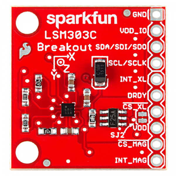
The LSM303C 6 DOF Breakout has 10 plated through hole connections.
The following table summarizes all of the plated through hole connections on the breakout board:
| Pin Label | Pin Function | Notes |
|---|---|---|
| GND | Ground reference | +0V |
| VDD_IO | Power supply for I/O pins | 1.71V up to VDD + 0.1V |
| SDA/ SDI/ SDO | I2C serial data SPI serial data input 3-wire interface serial data output | ST calls the second serial interface SPI, but it's really a half-duplex variant that uses the same pin for MISO and for MOSI. Note that all 3 data signals are the same pin. |
| SCL/ SCLK | I2C serial clock SPI serial port clock | 100 or 400 kHz I2C Up to 10 MHz SPI |
| INT_XL | Accelerometer interrupt signal | The functions, the threshold and the timing of this interrupt are configurable. |
| DRDY | Data ready | Configurable output to indicate when accelerometer or magnetometer data is ready. |
| CS_XL | Accelerometer: SPI enable I2C/SPI mode selection | 1: SPI idle mode / I2C communication enabled; 0: SPI communication mode / I2C disabled |
| VDD | Power supply | 1.9V to 3.6V |
| CS_MAG | Magnetometer: SPI enable I2C/SPI mode selection |
1: SPI idle mode / I2C communication enabled; 0: SPI communication mode / I2C disabled |
| INT_MAG | Magnetometer interrupt signal | The functions, the threshold and the timing of this interrupt are configurable. |
Power Supply
The LSM303C breakout has three power supply plated thru-hole connections: a 0V reference (GND), a core supply (VDD), and an IO supply (VDD_IO). The core of the IC can be powered from 1.9-3.6V. The IO must be given a potential of at least 1.71V up to the core supply voltage plus 0.1V. This dual supply setup eliminates the need for external voltage level translation. A 3.3V rail can power most of the device while still being able to communicate with a 1.8V processor without drawing all of its power from that lower voltage rail.
Communication
The LSM303C communicates over I2C or 'SPI' using the same plated thru-hole connections. The implementation of 'SPI' on the LSM303C isn't standard; it's a half-duplex variant. Standard SPI has a MOSI and a MISO signal. Both of these are found on the single SDA/SDI/SDO connection. The more common Arduino variants don't have hardware that directly supports this, so we are bit banging in our library. Your system may be compatible, so we didn't add external components to get the hardware to work with the Atmel SPI hardware. This connection is also used as the SDA connection for I2C. Testing showed that the implementation of this IO acts like an open-drain like is common with I2C. This means that a pull-up resistor is needed for both SPI and I2C. The breakout includes this pull-up. Both communication modes share the same clock line (SCL/SCLK).
The LSM303C is implemented as two separate cores on the same die. The accelerometer and magnetometer have their own chip select lines. In I2C mode, they have their own unique addresses. The accelerometer is at 0x1D, and the magnetometer is at 0x1E.
Interrupts
There are a variety of interrupts on the LSM303C. The system can be configured to generate an interrupt signal for free-fall, motion detection and magnetic field detection. The actual function of the two interrupt pins (INT_XL & INT_MAG) are highly configurable through either the I2C or SPI interfaces. They can be active high or low, latching or non-latching, etc. This advanced topic won't be covered in this hookup guide. Please reference the datasheet for more information.
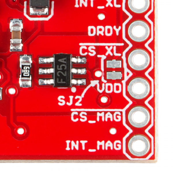
The Jumper
In many cases, especially Arduino related, you won't have multiple lower voltage rails. For these cases we've included SJ2. Your board comes with this jumper closed with a trace by default. This connects VDD_IO and VDD.
The intention of this jumper is to allow the end user to power use the board and begin developing right out of the box. To disable any of these jumpers, whip out your handy hobby knife, and carefully cut the small traces between the two pads. You may then connect VDD_IO to whatever power rial you desire.

