LS20031 5Hz (66 Channel) GPS Receiver Hookup Guide
 bboyho
Hardware Hookup
The simplest method of reading the serial UART output from a GPS receiver is to use a USB-to-serial converter (i.e. an FTDI). However, you can also use a microcontroller to read the output for embedded projects. For the scope of the tutorial, we will focus on two methods of connecting to the GPS receiver. Let's get started.
USB-to-Serial Converter
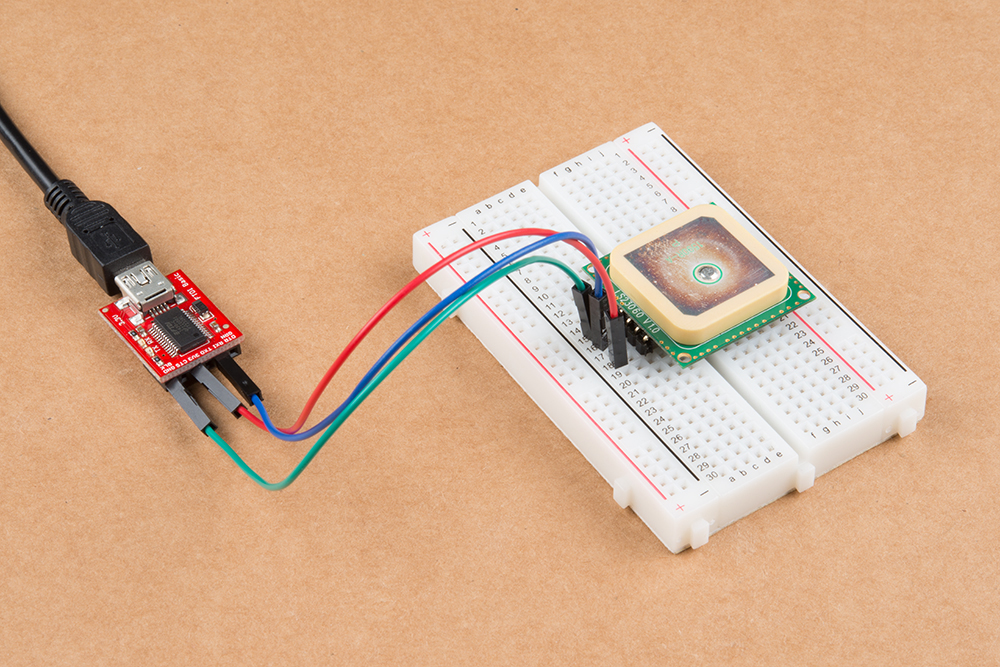
For quick tests, you can use a 3.3V usb-to-serial converter. Simply connect a 3.3V FTDI breakout board to the following pins listed below. On an FTDI, there is only one GND pin available. Connecting one GND pin is sufficient. To read the NMEA sentences, it is not necessary to connect the GPS receiver's Rx pin to the FTDI unless you are configuring the GPS receiver. For this tutorial, we will just need to connect the GPS receiver's Tx pin to the Rx of your FTDI.
| LS20031 (Top View Starting from the Left) |
3.3V FTDI Breakout Board |
|---|---|
| GND | GND |
| GND | GND |
| Tx (3.3V TTL) | Rx |
| Rx (3.3V TTL) | Tx |
| Vcc | 3.3V |
Microcontroller
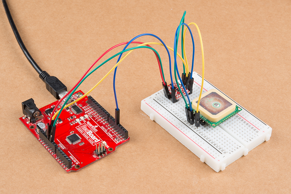
In order to retrieve data from the GPS module and do anything meaningful with the data in an embedded project, we will connect it to an Arduino. The LS20031 requires 3.3V for power and according to the product pages requires 41mA of current so we can use the Arduino's 3.3V pin for power as that can supply up to 50mA. The only complication with using the module connected to a standard 5V Arduino is that the module can only communicate with a maximum of 3.3V. To safely and reliably communicate with the 5V Arduino, we will be using a logic level converter.
| LS20031 (Top View Starting from the Left) |
Logic Level Converter (Low Side) | Logic Level Converter (High Side) | Arduino Uno (Atmega328P) Pin |
|---|---|---|---|
| GND | GND | GND | GND |
| GND | GND | GND | GND |
| Tx (3.3V TTL) | LV1 | HV1 | D4 |
| Rx (3.3V TTL) (optional) |
LV4 (optional) |
HV4 (optional) |
D3 (optional) |
| Vcc | LV | 3.3V | |
| HV | 5V |