LS20031 5Hz (66 Channel) GPS Receiver Hookup Guide
 bboyho
Examples
Example 1: Quick Test
For a quick test, let's connect to the LS20031 GPS receiver to view the NMEA sentences. You can use either of the two connection options below.
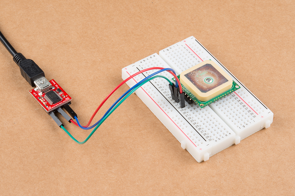
a.) USB-to-Serial Converter
One option is to connect a 3.3V FTDI to the LS20031 GPS receiver.
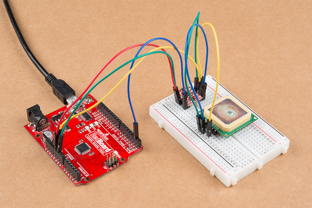
b.) Microcontroller
You can also use the USB-to-serial converter on an Arduino-compatible device as long as you configure the hardware UART pins to inputs. Once set as an input, there will not be any bus contention between the ATmega, FTDI, and the GPS receiver. Copy the code below and upload to the Arduino. In this case, we will be using a RedBoard programmed with Arduino.
language:c
/*
  SerialBridge.ino

  Written by: Mike Hord
  Date: 3/8/2013

  Description: Simple sketch to turn an Arduino-compatible device into a
  USB-to-serial bridge.

  NOTE: There is no need to include *any* Serial functions
  at all*. Doing so would only serve to override the
  pinMode() commands. The baud rate will be set by the
  computer when the serial program connects to the bridge
  device.
*/

void setup()
{
  // Make the RX/TX lines inputs, so they don't contend with
  //  the lines on the serial UART and cause data issues or damage.
  pinMode(0, INPUT);
  pinMode(1, INPUT);
}

void loop()
{
  // Nothing here, because we don't *need* anything here.
}
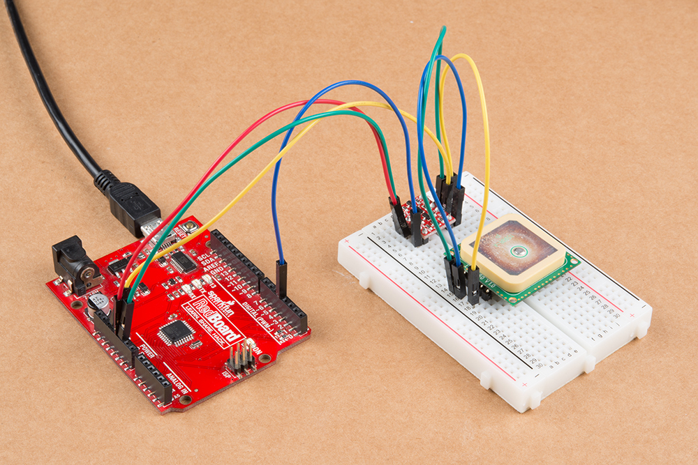
Then move the GPS receiver's Tx wire on the HV side of the logic level converter from pin 4 to pin 1.
Reading the NMEA Sentences
Open a serial monitor or terminal program at a baud rate of 57600. The information is displayed as NMEA sentences which the GPS module uses to communicate position information. You should see an output similar to the values below. If nothing is displayed, you'll need to double check your connections, soldering, and baud rate.
language:bash
$GPGGA,105317.709,8960.0000,N,00000.0000,E,0,0,,137.0,M,13.0,M,,*4C
$GPGLL,8960.0000,N,00000.0000,E,105317.709,V,N*49
$GPGSA,A,1,,,,,,,,,,,,,,,*1E
$GPGSV,1,1,00*79
$GPRMC,105317.709,V,8960.0000,N,00000.0000,E,0.00,0.00,010610,,,N*78
$GPVTG,0.00,T,,M,0.00,N,0.00,K,N*32
Open up the datasheet and try reading the sentences. Notice that the values between the delimiters (i.e. the commas ",") are empty? This is because the GPS receiver has not received a satellite lock yet. You will notice that the "V" is displayed on a few NMEA sentences (specifically the GPRMC sentences in the second field). This indicates that the data is invalid and there are not enough satellites in view. This should take a few seconds before you get a lock. Eventually, more fields will be filled in once the GPS receiver gathers enough information and achieves a satellite lock. You will also see a letter "A" indicating there is a valid lock.
language:bash
$GPGGA,065938.200,4005.9932,N,10509.9938,W,1,9,0.86,1562.8,M,-20.7,M,,*5C
$GPGLL,4005.9932,N,10509.9938,W,065938.200,A,A*4E
$GPGSA,A,3,17,28,30,01,13,24,15,11,06,,,,1.62,0.86,1.37*04
$GPGSV,4,1,13,17,80,265,43,28,62,054,36,19,48,235,,30,41,156,33*78
$GPGSV,4,2,13,48,35,219,29,01,33,058,25,13,28,250,41,11,22,048,29*70
$GPGSV,4,3,13,15,15,287,36,06,15,181,23,24,13,317,33,07,10,149,22*74
$GPGSV,4,4,13,22,01,079,*44
$GPRMC,065938.200,A,4005.9932,N,10509.9938,W,0.01,57.88,261118,,,A*47
$GPVTG,57.88,T,,M,0.01,N,0.01,K,A*0F
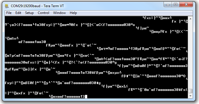
Baud rate mismatch (aka garbage) as described in this Common Pitfalls section.
Example 2: Software Serial Passthrough
This example is not as straight forward as other software serial passthroughs. When using software serial, users experienced problems with the default buffer size. To adjust the software serial library for the LS20031, you will need to head to the your Arduino's program folder. On a Windows, the path should be similar to the directory as shown below.
C:\Program Files\arduino-1.8.5\hardware\arduino\avr\libraries\SoftwareSerial\src
Open a text editing program to modify the SoftwareSerial.h file. Then look for this section of code near the top of the header:
#ifndef _SS_MAX_RX_BUFF
#define _SS_MAX_RX_BUFF 64 // RX buffer size
#endif
Adjust the buffer size of 64 by changing the value to 256 as shown below.
#ifndef _SS_MAX_RX_BUFF
#define _SS_MAX_RX_BUFF 256 // RX buffer size
#endif
Save the changes. If you have the Arduino IDE open, be sure to close it out. Open the Arduino back up (the version with the modified SoftwareSerial.h file). Copy and paste the code below. Select the Arduino board and COM port for your Arduino. Then click on upload.
language:c
/*
GPS_SerialPassthrough.ino
LS20031 GPS Receiver

By: Ho Yun "Bobby" Chan @ SparkFun Electronics
Date: November 25th, 2018

Description: This is a basic serial passthrough code that
sets up a software serial port to pass data between the a
GPS receiver and the serial monitor. This code should work
with any GPS receiver as long as you have the correct
baud rate.
*/

// We'll use SoftwareSerial to communicate with the FPS:
#include <SoftwareSerial.h>

// set up software serial pins for Arduino's w/ Atmega328P's
// GPS (TX) is connected to pin 4 (Arduino's Software RX)
// GPS (RX) is connected through a converter to pin 3 (Arduino's Software TX)
SoftwareSerial gps(4, 3); // (Arduino SS_RX = pin 4, Arduino SS_TX = pin 3)
static const uint32_t GPSBaud = 57600; //LS20031's Baud Rate

/*If using another Arduino microcontroller, please be aware of the
limitations listed in the library's note
=> https://www.arduino.cc/en/Reference/softwareSerial . Do
not forget to rewire the connection to the Arduino. if you do!*/

// GPS (TX) is connected to pin 11 (Arduino's Software RX)
// GPS (RX) is connected through a converter to pin 10 (Arduino's Software TX)
//SoftwareSerial gps(11, 10); // (Arduino SS_RX = pin 11, Arduino SS_TX = pin 10)

void setup()
{
  // Set up both ports at 115200 baud since that is the GPS's default baud.
  // Make sure the baud rate matches the config setting of SDK demo software.
  Serial.begin(115200); //set up Arduino's hardware serial UART
  gps.begin(57600);    //set up software serial UART for GPS
}

void loop()
{
  if (Serial.available())
  { // If data comes in from serial monitor, send it out to GPS
    gps.write(Serial.read());
  }
  if (gps.available())
  { // If data comes in from GPS, send it out to serial monitor
    Serial.write(gps.read());
  }
}
If you have not already, make sure to have the GPS Receiver's Tx wire on the HV side of the logic level converter on pin 4.
Open a serial monitor at a baud rate of 115200. You should see an output similar to the values below like example 1. Remember the values shown below are actually not valid yet because there is not a satellite lock. This should take a few seconds. If nothing is displayed, you'll need to double check your connections, soldering, and baud rate.
language:bash
$GPGGA,105317.709,8960.0000,N,00000.0000,E,0,0,,137.0,M,13.0,M,,*4C
$GPGLL,8960.0000,N,00000.0000,E,105317.709,V,N*49
$GPGSA,A,1,,,,,,,,,,,,,,,*1E
$GPGSV,1,1,00*79
$GPRMC,105317.709,V,8960.0000,N,00000.0000,E,0.00,0.00,010610,,,N*78
$GPVTG,0.00,T,,M,0.00,N,0.00,K,N*32
    $GPGGA,014646.400,4001.0409,N,10515.1451,W,2,8,0.94,1614.5,M,-20.6,M,0000,0000*5A
    $GPGLL,4001.0409,N,10515.1451,W,016640,D4
    GGAM,2,020,30,82,,1600412*
    $GGV3,13,01420,9,02,6709,703,8,5*
    $PS,2,173,1,,0,41,42,0072,,6,93*2
    PSV3313,9211,2210,78,*6$PRC0664,A40.4,,51541W.217.061,,D7
    $VG1.5,,M.2N0.,,*
Example 3: TinyGPSPlusPlus - DeviceExample.ino
With the TinyGPS++ Arduino Library installed, open the Arduino IDE. Open the example DeviceExample.ino by clicking on File > Examples > TinyGPS++ > DeviceExample. Once open, update software serial's baud rate to 56700 by modifying this line of code from:
language:c
static const uint32_t GPSBaud = 4800;
to
language:c
static const uint32_t GPSBaud = 57600;
Select the correct board definition and COM port. Make sure that your the the GPS receiver's output is connected to pin 4. Then open the serial monitor. The example code outputs a different baud rate to your computer's serial port so make sure that set at 115200. Your output should look similar to the reading below when there is a lock.

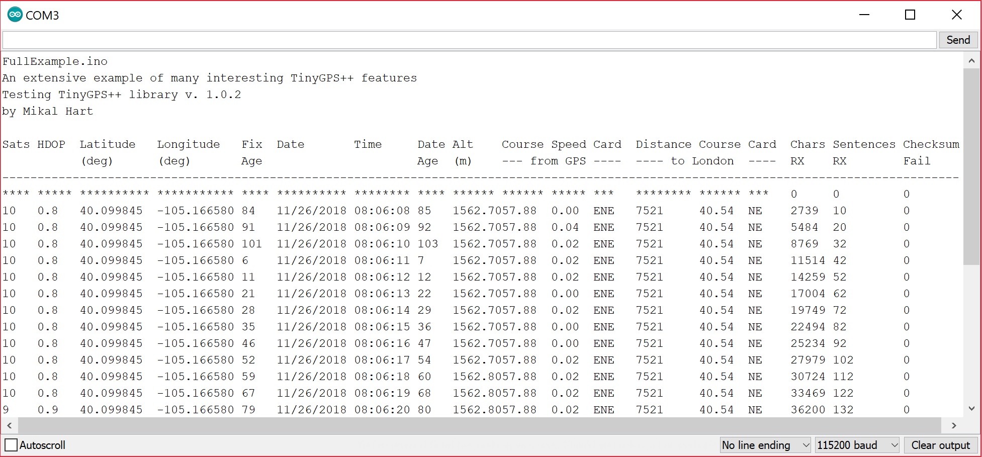
Example 4: TinyGPSPlusPlus - FullExample.ino
With the TinyGPS++ Arduino Library installed, open the Arduino IDE. Open the example FullExample.ino by clicking on File > Examples > TinyGPS++ > FullExample. You will also need to update the software serial's baud rate by setting it to 56700. Modify this line of code from:
language:c
static const uint32_t GPSBaud = 4800;
to
language:c
static const uint32_t GPSBaud = 57600;
Select the correct board definition and COM port. Again, make sure that your the the GPS receiver's output is connected to pin 4. Then open the serial monitor. The example code outputs a different baud rate to your computer's serial port so make sure that set at 115200. Your output should look similar to the reading below when there is a lock.
Moar Examples!
If you check out the TinyGPSPlus examples folder, you will notice that there are more examples listed in the TinyGPSPlus library! Browse through the code, adjust as necessary when testing the examples before applying it to your next project!