$7.75
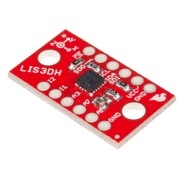
The LIS3DH is a triple axis accelerometer you can use to add translation detection to your project. The "3D" in LIS3DH refers to the fact that it is a 3DoF, or 3 Degrees of Freedom. Additionally, it has a few analog inputs to play with, and it has some built in movement detection features to detect things like free-fall, and to indicate if the FIFO buffers are full.
If you're looking for something small and inexpensive, and are only measuring acceleration, this is the product for you. Other inertial measurement units (or IMUs), such as the LSM9DS1; the LSM6DS3; or the LSM303C, can provide additional space location data such as gyroscopic or magnetometric.
This guide presents the basics of plugging the board into a RedBoard, shows how to use the Arduino library to get acceleration data live or by FIFO collection, and describes the library usage.
To follow along, you'll need the following materials:
A logic level shifter is required for any 5V-operating Arduino (UNO, RedBoard, Leonardo, etc). If you use a 3.3V-based 'duino -- like the Arduino Pro 3.3V or 3.3V Pro Mini -- there is no need for level shifting.
If you're not familiar with some of the concepts below, we recommend checking out that tutorial before continuing on.
Also, the following ST documents are helpful for advanced users:
There are a few different methods with which you can use the LIS3DH.
The top side of the board has the LIS3DH sensor, some bypass caps and pull-up resistors.
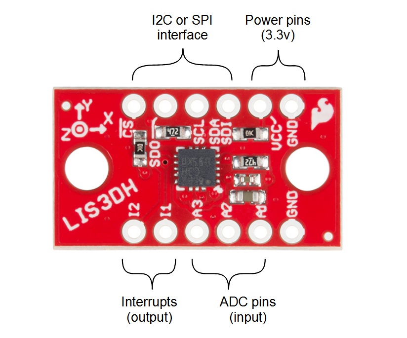
This table gives more information as to each pins functionality. The serial port can be connected as either SPI or I2C, and it uses the same physical pins for both. To get going, just wire up your choice of interface, supply 3.3v, and ground. Note that you will not need to use all the pins no matter which communication method you choose.
| Connection | |||||
|---|---|---|---|---|---|
| Group | Name | Direction | Description | I2C | SPI |
| Serial | !CS | I | Chip select (for SPI) | NC | !CS |
| SDO | O | Data output (MISO for SPI) | NC | MISO | |
| SCL | I | Data clock | SCL | SCK | |
| SDA/SDI | I/O | Data in (SDA for I2C, MOSI for SPI) | SDA | MOSI | |
| Interrupts | I1 | O | Primary int has FIFO + motion | Optional MCU | |
| I2 | O | Secondary int has motion | Optional MCU | ||
| ADC | A1 | I | Analog in | Optional | |
| A2 | I | Analog in | Optional | ||
| A3 | I | Analog in (unused for temp readings) | Optional | ||
| Power | VCC | I | 3.3V input | Supply | |
| GND | I | Ground connection (either PTH) | Supply | ||
On the bottom, there are two jumpers that correspond to the I2C address and pull-up enable.
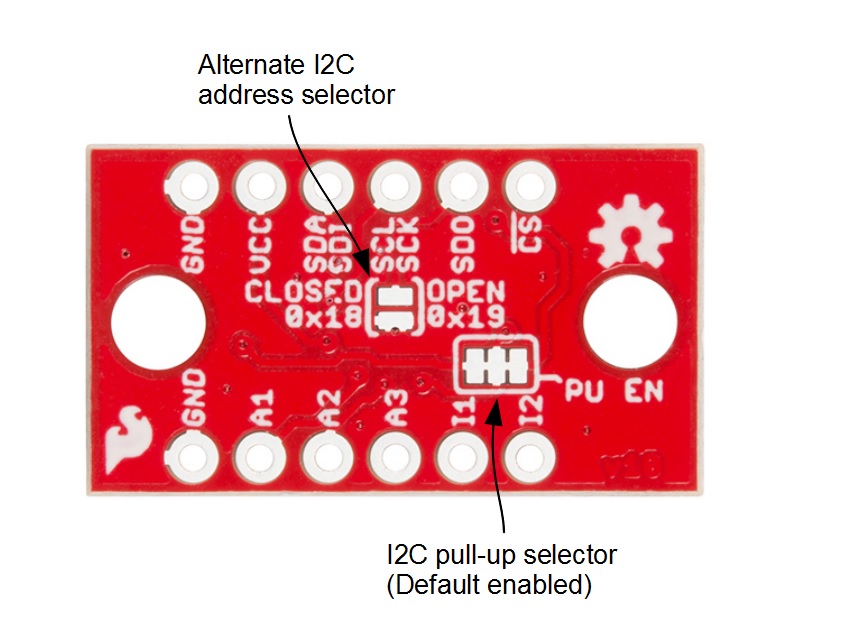
The following options are available:
This sensor works nicely with a breadboard for easy connection, and, because it gives some mass to the accelerometer, it more closely matches what might be expected from a project or cellphone.
To add headers, break off two 6-pin lengths of 0.1 inch male headers, and set them into a breadboard to use as a soldering jig.
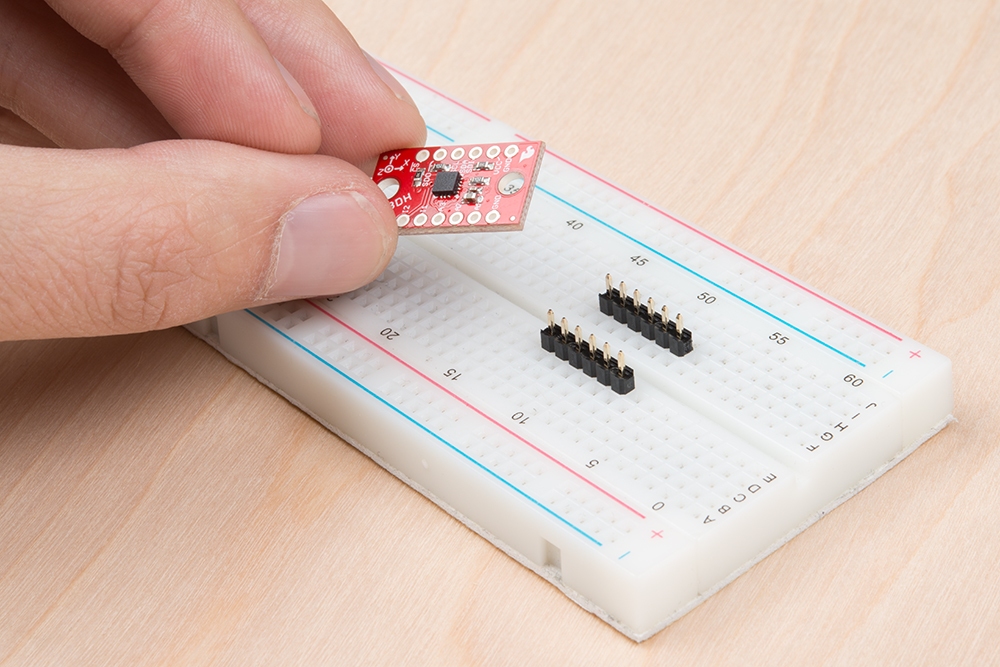
Drop the breakout board onto the pins, and solder down the rows.
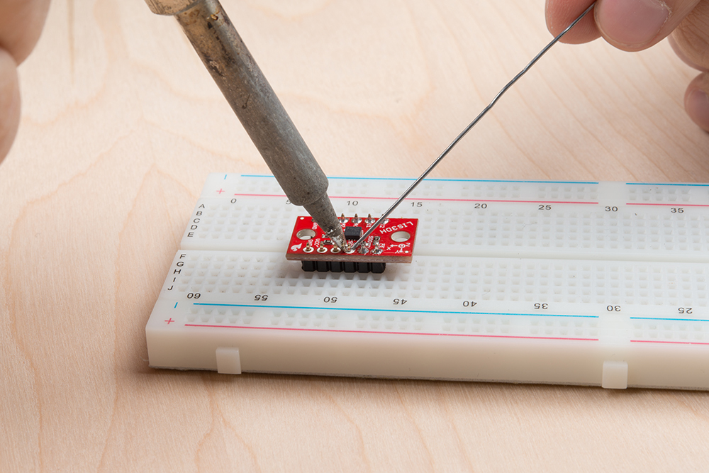
Congratulations! You're now ready to connect the sensor to a microcontroller of your choosing.
The examples in the guide use the Arduino IDE and a RedBoard to communicate with the LIS3DH.
To get the Arduino library, download from Github, or use the Arduino Library Manager.
Visit the GitHub repository to download the most recent version of the library, or click the link below:
For help installing the library, check out our How To Install An Arduino Library tutorial.
If you don't end up using the manger, you'll need to move the SparkFun_LIS3DH_Arduino_Library folder into a libraries folder within your Arduino sketchbook.
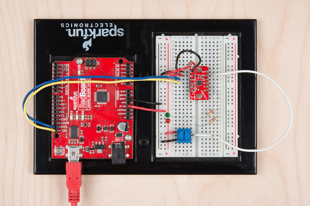
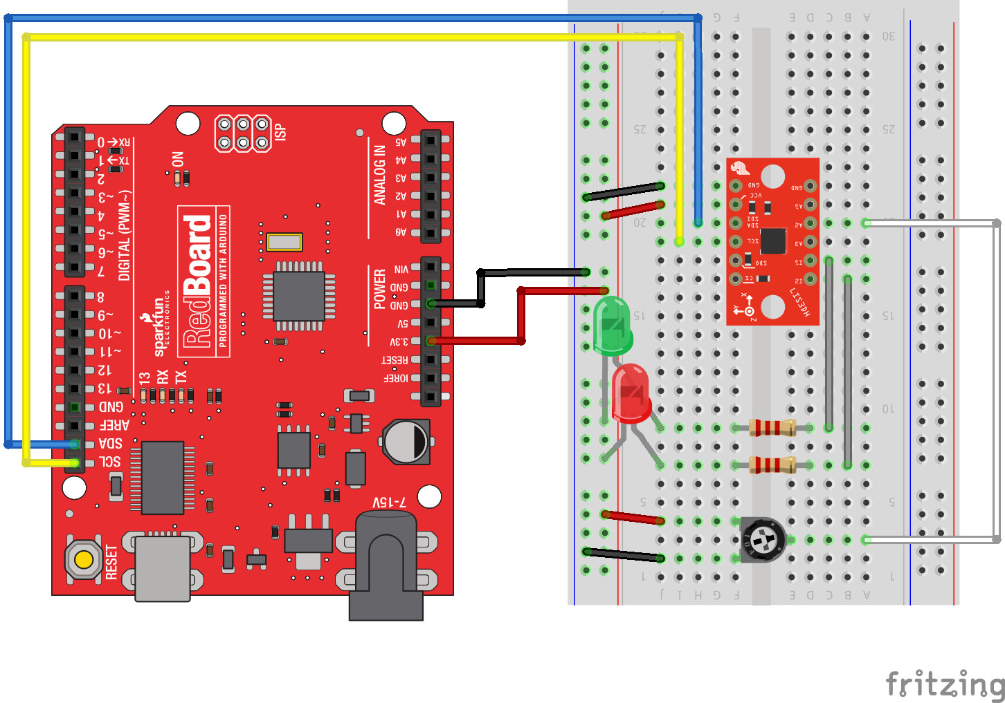
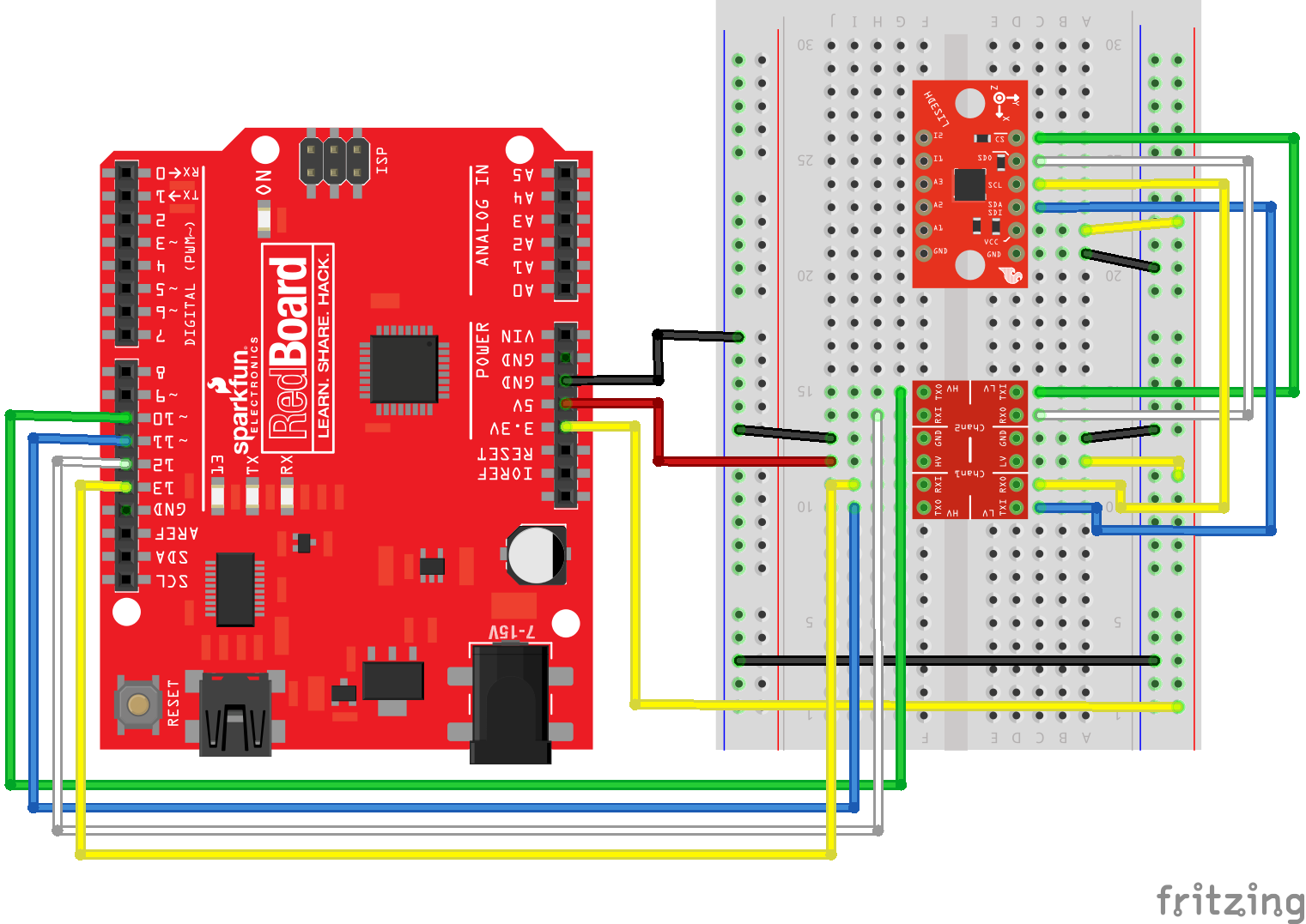
The first circuit allows a RedBoard to talk to the LIS3DH over I2C and provides connections on the interrupt and ADC pins.
The interrupts are useful to indicate conditions like extreme Gs or freefall, and to tell the RedBoard that the FIFO is full and needs to be serviced. The analog input pins are useful to measure various voltages similar to the RedBoard's analog inputs, but have a more constrained voltage range (about 0.9V to 1.8V). If you don't need either of these, just connect power, ground, and communication pins, and ignore the interrupt and ADC examples.
Use these two pictures as a guide for building the circuit.
Start with just the basic accelerometer sketch, also called "MinimalistExample" from the library. This will periodically samples the sensor and displays data as number of Gs detected. Remember, the vertical axis will read 1G while sitting at rest.
language:c
#include "SparkFunLIS3DH.h"
#include "Wire.h"
#include "SPI.h"

LIS3DH myIMU; //Default constructor is I2C, addr 0x19.

void setup() {
  // put your setup code here, to run once:
  Serial.begin(9600);
  delay(1000); //relax...
  Serial.println("Processor came out of reset.\n");

  //Call .begin() to configure the IMU
  myIMU.begin();

}


void loop()
{
  //Get all parameters
  Serial.print("\nAccelerometer:\n");
  Serial.print(" X = ");
  Serial.println(myIMU.readFloatAccelX(), 4);
  Serial.print(" Y = ");
  Serial.println(myIMU.readFloatAccelY(), 4);
  Serial.print(" Z = ");
  Serial.println(myIMU.readFloatAccelZ(), 4);

  delay(1000);
}
Example output:
Processor came out of reset.


Accelerometer:
 X = -0.1481
 Y = -0.1361
 Z = 0.9768

Accelerometer:
 X = -0.1481
 Y = -0.1361
 Z = 0.9768

Accelerometer:
 X = -0.1481
 Y = -0.1361
 Z = 0.9768

Accelerometer:
 X = -0.1481
 Y = -0.1361
 Z = 0.9768
When run, the sketch will display data in Gs to the serial terminal. Every second, the data is collected and printed.
To try out the analog inputs, load the example called "ADCUsage", or copy paste from the following section. This example also shows some of the additional settings that can be applied within the begin() function.
language:c
#include "SparkFunLIS3DH.h"
#include "Wire.h"
#include "SPI.h"

LIS3DH myIMU; //Default constructor is I2C, addr 0x19.

void setup() {
  // put your setup code here, to run once:
  Serial.begin(9600);
  delay(1000); //relax...
  Serial.println("Processor came out of reset.\n");

  myIMU.settings.adcEnabled = 1;
  //Note:  By also setting tempEnabled = 1, temperature data is available
  //on ADC3.  Temperature *differences* can be read at a rate of
  //1 degree C per unit of ADC3
  myIMU.settings.tempEnabled = 0;
  myIMU.settings.accelSampleRate = 50;  //Hz.  Can be: 0,1,10,25,50,100,200,400,1600,5000 Hz
  myIMU.settings.accelRange = 2;      //Max G force readable.  Can be: 2, 4, 8, 16
  myIMU.settings.xAccelEnabled = 0;
  myIMU.settings.yAccelEnabled = 0;
  myIMU.settings.zAccelEnabled = 0;

  //Call .begin() to configure the IMU
  myIMU.begin();

}

void loop()
{
  //Get all parameters
  Serial.print("\nADC:\n");
  Serial.print(" 1 = ");
  Serial.println(myIMU.read10bitADC1());
  Serial.print(" 2 = ");
  Serial.println(myIMU.read10bitADC2());
  Serial.print(" 3 = ");
  Serial.println(myIMU.read10bitADC3());

  delay(300);
}
Example output:
Processor came out of reset.


ADC:
 1 = 1020
 2 = 522
 3 = 506

ADC:
 1 = 1020
 2 = 544
 3 = 516

ADC:
 1 = 1020
 2 = 540
 3 = 517
The sketch prints the three ADC values every 300ms. Move the knob to see how the values change and how the effective voltage range is somewhat in the middle of the full range. Move the wire from on ADC pin to another to see that the controlled value changes.
Interrupt behavior is highly configurable and is thus omitted as basic library functions. Instead, LIS3DH registers are directly written in accordance with the datasheet.
An example is provided that has the relevant registers configured with comments in a template function that can be copied into a project and modified. Run the example named IntUsage, which will throw an interrupt on one pin when an exceeded acceleration is detected and a pulse on the other when a tap is detected.
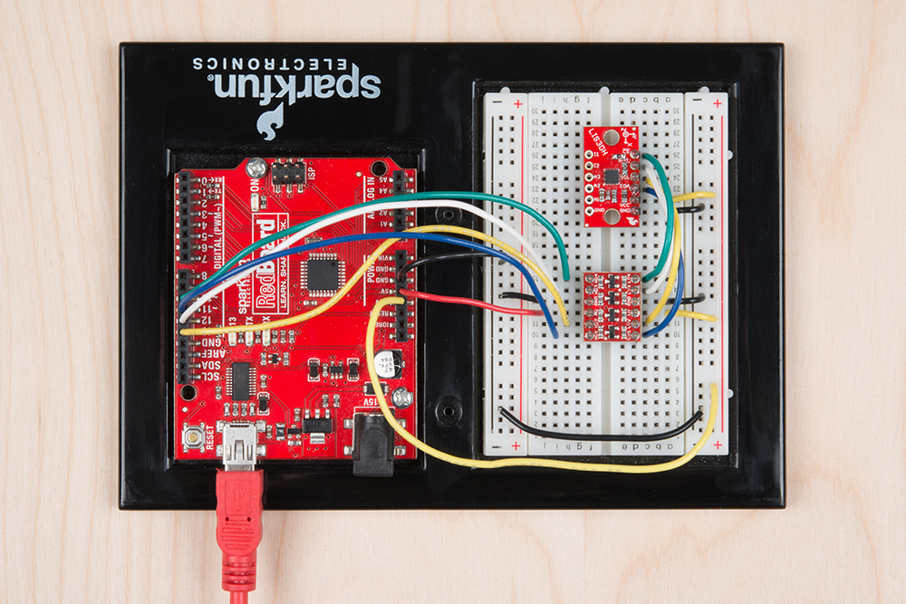
The second method in which to communicate with the LIS3DH is with the SPI interface. The SPI interface operates at 3.3v, so use a logic level converter or a MCU that operates at 3.3V. Use the following pictures to help build the circuit.
SPI is not the default configuration, so you'll have to pass extra information to the library by constructing with parameters. Modify "MinimalistExample" by changing LIS3DH myIMU; to LIS3DH myIMU(SPI_MODE, 10); for SPI mode with the !CS pin connected to pin 10.
The modified "MinimalistExample" is listed here:
language:c
#include "SparkFunLIS3DH.h"
#include "Wire.h"
#include "SPI.h"

LIS3DH myIMU(SPI_MODE, 10); // constructed with parameters for SPI and cs pin number

void setup() {
  // put your setup code here, to run once:
  Serial.begin(9600);
  delay(1000); //relax...
  Serial.println("Processor came out of reset.\n");

  //Call .begin() to configure the IMU
  myIMU.begin();

}


void loop()
{
  //Get all parameters
  Serial.print("\nAccelerometer:\n");
  Serial.print(" X = ");
  Serial.println(myIMU.readFloatAccelX(), 4);
  Serial.print(" Y = ");
  Serial.println(myIMU.readFloatAccelY(), 4);
  Serial.print(" Z = ");
  Serial.println(myIMU.readFloatAccelZ(), 4);

  delay(1000);
}
Example output:
Processor came out of reset.


Accelerometer:
 X = -0.1481
 Y = -0.1361
 Z = 0.9768

Accelerometer:
 X = -0.1481
 Y = -0.1361
 Z = 0.9768

Accelerometer:
 X = -0.1481
 Y = -0.1361
 Z = 0.9768

Accelerometer:
 X = -0.1481
 Y = -0.1361
 Z = 0.9768
When run, the sketch will display data in Gs to the serial terminal. Every second, the data is collected and printed.
The SPI bus can operate faster than I2C, so for high speed data collections where periodic sampling is required, SPI is advisable.
language:c
#include "SparkFunLIS3DH.h"
#include "Wire.h"
#include "SPI.h"

LIS3DH myIMU(SPI_MODE, 10); //Constructing with SPI interface information
//LIS3DH myIMU(I2C_MODE, 0x19); //Alternate constructor for I2C

uint32_t sampleNumber = 0; //Used to make CSV output row numbers

void setup() {
  // put your setup code here, to run once:
  Serial.begin(9600);
  delay(1000); //relax...
  Serial.println("Processor came out of reset.\n");

  myIMU.settings.adcEnabled = 0;
  //Note:  By also setting tempEnabled = 1, temperature data is available
  //instead of ADC3 in.  Temperature *differences* can be read at a rate of
  //1 degree C per unit of ADC3 data.
  myIMU.settings.tempEnabled = 0;
  myIMU.settings.accelSampleRate = 10;  //Hz.  Can be: 0,1,10,25,50,100,200,400,1600,5000 Hz
  myIMU.settings.accelRange = 2;      //Max G force readable.  Can be: 2, 4, 8, 16
  myIMU.settings.xAccelEnabled = 1;
  myIMU.settings.yAccelEnabled = 1;
  myIMU.settings.zAccelEnabled = 1;

  //FIFO control settings
  myIMU.settings.fifoEnabled = 1;
  myIMU.settings.fifoThreshold = 20;  //Can be 0 to 31
  myIMU.settings.fifoMode = 1;  //FIFO mode.
  //fifoMode can be:
  //  0 (Bypass mode, FIFO off)
  //  1 (FIFO mode)
  //  3 (FIFO until full)
  //  4 (FIFO when trigger)

  //Call .begin() to configure the IMU (except for the fifo)
  myIMU.begin();

  Serial.print("Configuring FIFO with no error checking...");
  myIMU.fifoBegin(); //Configure fifo
  Serial.print("Done!\n");

  Serial.print("Clearing out the FIFO...");
  myIMU.fifoClear();
  Serial.print("Done!\n");
  myIMU.fifoStartRec(); //cause fifo to start taking data (re-applies mode bits)

}

void loop()
{
  //float temp;  //This is to hold read data
  //uint16_t tempUnsigned;
  //
  while(( myIMU.fifoGetStatus() & 0x80 ) == 0) {};  //Wait for watermark

  //Now loop until FIFO is empty.
  //If having problems with the fifo not restarting after reading data, use the watermark
  //bits (b5 to b0) instead.
  //while(( myIMU.fifoGetStatus() & 0x1F ) > 2) //This checks that there is only a couple entries left
  while(( myIMU.fifoGetStatus() & 0x20 ) == 0) //This checks for the 'empty' flag
  {
      Serial.print(sampleNumber);
      Serial.print(",");
      Serial.print(myIMU.readFloatAccelX());
      Serial.print(",");
      Serial.print(myIMU.readFloatAccelY());
      Serial.print(",");
      Serial.print(myIMU.readFloatAccelZ());
      Serial.println();
      sampleNumber++;
  }

}
Example output:
Processor came out of reset.

Configuring FIFO with no error checking...Done!
Clearing out the FIFO...Done!
0,-0.15,-0.14,1.04
1,-0.17,-0.12,1.02
2,-0.21,-0.10,0.95
3,-0.21,-0.10,1.01
4,-0.22,-0.12,1.07
5,-0.17,-0.12,0.99
6,-0.12,-0.15,0.96
7,-0.18,-0.12,0.94
8,-0.19,-0.10,0.98
9,-0.20,-0.14,1.04
10,-0.19,-0.12,0.99
11,-0.20,-0.10,0.95
12,-0.21,-0.12,1.06
13,-0.14,-0.12,0.98
14,-0.10,-0.11,0.95
15,-0.12,-0.10,0.94
16,-0.14,-0.09,0.90
...
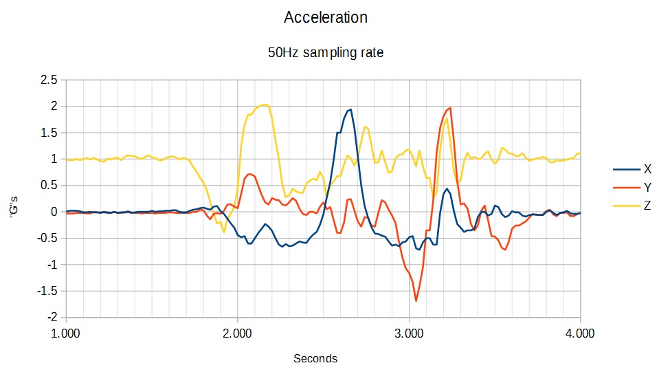
Notice that the output produces batches of data periodically. Even though the data waits to be collected, it is still sampled periodically. The data is collected when the FIFO is past the watermark configured in the line myIMU.settings.fifoThreshold = 20;.
The following examples are included in the Arduino library:
Take the following steps to use the library
.begin()Example:
language:c
LIS3DH myIMU; //This creates an instance the library object.

void setup()
{
    myIMU.settings.adcEnabled = 1;
    myIMU.settings.tempEnabled = 0;
    myIMU.settings.accelSampleRate = 50;  //Hz.  Can be: 0,1,10,25,50,100,200,400,1600,5000 Hz
    myIMU.settings.accelRange = 2;      //Max G force readable.  Can be: 2, 4, 8, 16
    myIMU.begin();
}
The main LIS3DH class has a public member, which is named settings. To configure settings, use the format myIMU.settings.accelSampleRate = (...);. Then, call .begin() to apply.
Settings contains the following members:
uint8_t adcEnabled -- Set to 1 to enable ADCsuint8_t tempEnabled -- Set to 1 to override ADC3 with delta temperature informationuint16_t accelSampleRate -- Can be: 0,1,10,25,50,100,200,400,1600,5000 Hzuint8_t accelRange -- Max G force readable. Can be: 2, 4, 8, 16uint8_t xAccelEnabled -- Set to 1 to enable x axisuint8_t yAccelEnabled -- Set to 1 to enable y axisuint8_t zAccelEnabled -- Set to 1 to enable z axisuint8_t fifoEnabled -- Set to 1 to enable FIFOuint8_t fifoMode -- Can be 0x0,0x1,0x2,0x3uint8_t fifoThreshold -- Number of bytes read before watermark is detected (0 to 31)Call after providing settings to start the wire or SPI library as indicated by construction and runs applySettings(). Returns 0 for success.
This configures the IMU's registers based on the contents of .settings.
These functions return axis acceleration information as a 16 bit, signed integer.
These functions call the Raw functions, then apply math to convert to a float expressing acceleration in number of Gs.
These functions return the ADC values read from the pins. Values will be 10 bit and the detectable range is about 0.9V to 1.8V.
Note: When tempEnabled == 1, ADC3 reads as an unreferenced temperature in degrees C. Read twice and calculate the change in temperature.
This enables the FIFO by writing the proper values into the FIFO control reg, and control reg 5. This does not start the data collection to the FIFO, run fifoStartRec() when ready.
Sample rate depends on data rate selected in .settings.
This reads all data until the status says none is available, discarding the data. Use to start with new data if the FIFO fills with old data.
This enables FIFO data collection. Run this before starting to check if data is available.
After fifoStartRec is used, data from the X, Y, Z registers is not real time, but is the next available sample.
This returns the FIFO status byte. The contents of the byte are as follows:
This stops the FIFO and returns the device to regular operation.
You should now have a basic understanding of how to use the LIS3DH, but if you need some more information check out the following links:
Need a little inspiration? Check out some of these other great SparkFun tutorials.
learn.sparkfun.com | CC BY-SA 3.0 | SparkFun Electronics | Niwot, Colorado