LilyPad Tri-Color LED Hookup Guide
 Gella
Gella 
Attaching to a LilyPad Arduino
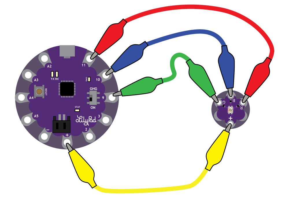
To follow along with the code examples in this tutorial, connect the tri-color LED to a LilyPad Arduino as shown below. Use alligator clips to temporarily connect the R (Red) tab on the LED to 11, G (Green) to 9, B (Blue) to 10, and (+) to (+). When you are finished prototyping, replace the alligator clips with conductive thread traces for permanent installation in your project.
Note: To follow along with the Custom Color Mixing example code, you will need to attach the R, G, and B tabs to a sew tabs on the LilyPad with PWM capabilities.
Additional Board Hookup
If you'd like to use the tri-color LED with the LilyPad ProtoSnap Plus, attach the R, G, and B tabs to the ProtoSnap's expansion ports. Only port 10 has PWM capabilities, so you will not be able to follow along with the Custom Color Mixing example unless you snap the ProtoSnap Plus apart and connect the tri-color LED directly to tabs on the LilyPad USB Plus.
If using the the pre-wired tri-color LED on the ProtoSnap - LilyPad Development Board, the connection is different than what was explained earlier. R is attached to 9, G is attached to 11, and B is attached to 10. We recommend checking out the LilyPad Development Board Activity Guide for step-by-step examples using this LED.