LilyPad RGB LED Hookup Guide
 bboyho
 Gella
Gella Introduction
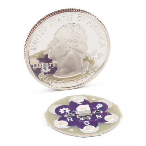
The LilyPad RGB LED is a specialty board that can produce a variety of colors. On the board is an RGB (red-green-blue) LED, made of three tiny LEDs connected together. Each of the colors in the RGB LED are connected to one of the sew tabs on the board labeled R, G, and B.
Required Materials
To follow along with the code examples, we recommend:
Suggested Reading
To add this LED to a project, you should be comfortable sewing with conductive thread and uploading code to your LilyPad Arduino (for the programming examples). Here are some tutorials to review before working with this part:
What is a Circuit?
Light
Insulation Techniques for e-Textiles
Getting Started with LilyPad
The color channels on this RGB LED are all connected through a common cathode (negative) pin. This configuration means that the individual red, green, and blue LEDs share a common ground tab. To light up each color individual LED, connect them each to a power source. For simple circuit hookups, this means you need to connect the R, G, or B sew tabs to power (+) and in code set them to HIGH (for digital output) or 255 (for analog output) to turn them on.
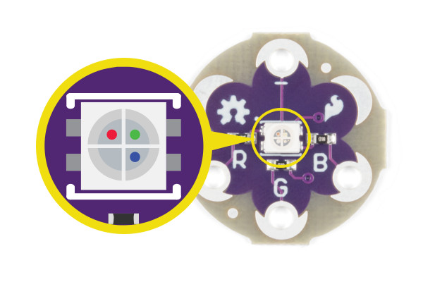
If you look closely you can see the individual LEDs inside the package.
Using in a Simple E-Sewing Project
The RGB LED doesn't need to be connected to a microcontroller in order to control it. Here are some examples of using simple circuits to mix colors with the LED.
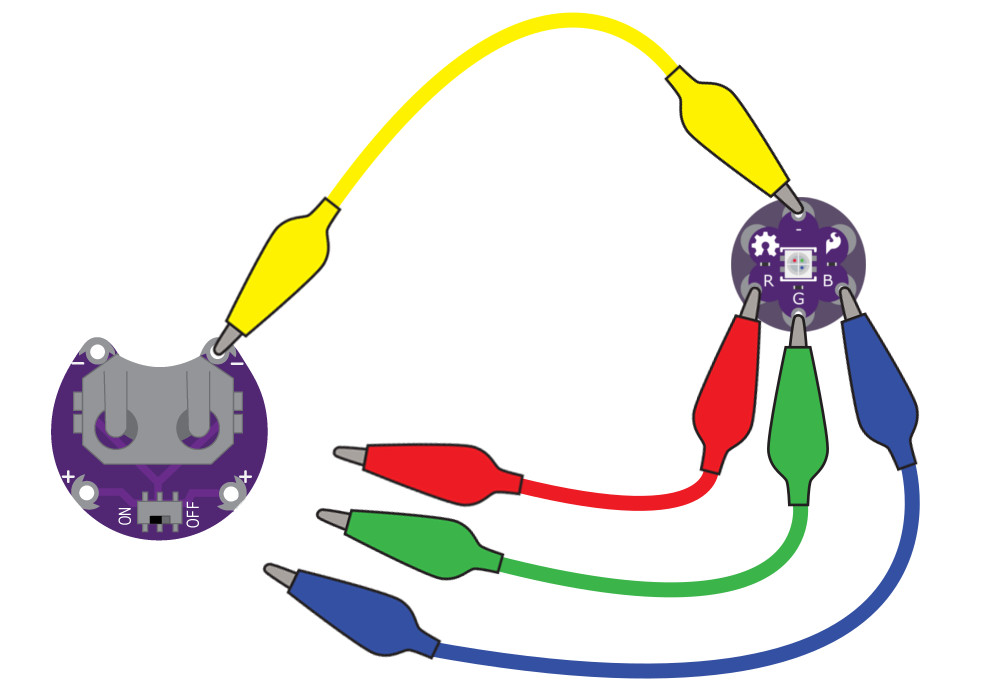
To experiment with basic color mixing, you can use alligator clips on the RGB LED's sew tabs to temporarily connect them to a power source, such as a LilyPad Coin Cell Battery Holder with a coin cell battery. Connect the negative tab (-) to the negative sew tab on the battery holder with a clip, and each color tab R (Red), G (Green), and B (Blue) to the postivie tab (+) to connect them. The combination of color sew tabs that are connected to power will create a variety of colors.
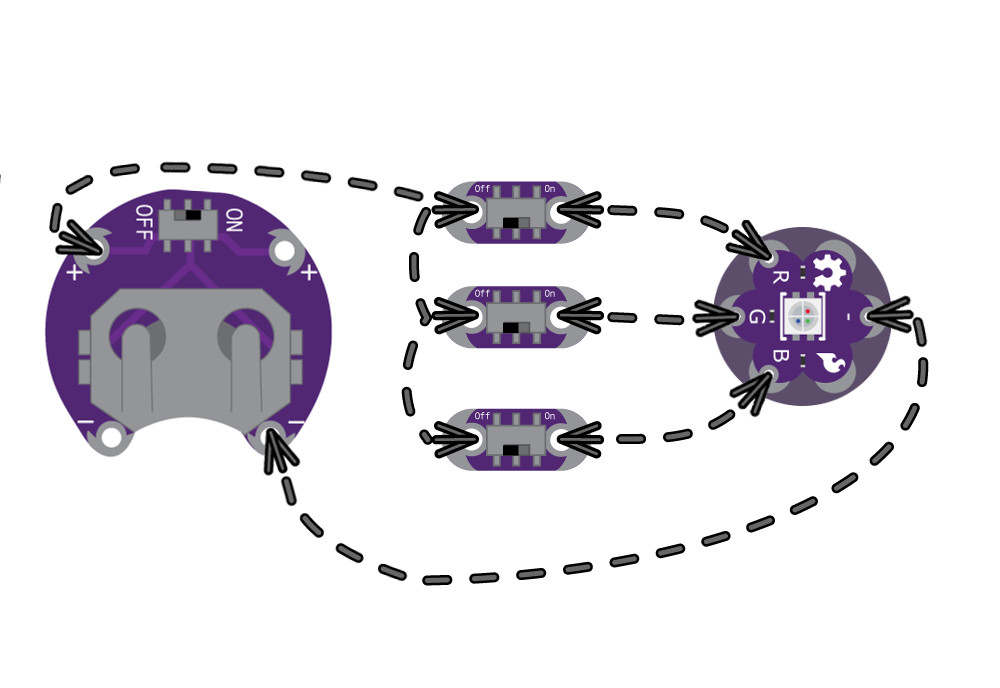
You can replace these connections with switches or buttons for a simple color mixing circuit. After prototyping and testing a project with the RGB LED, you can replace the connections with conductive thread in your project.
Attaching to a LilyPad Arduino
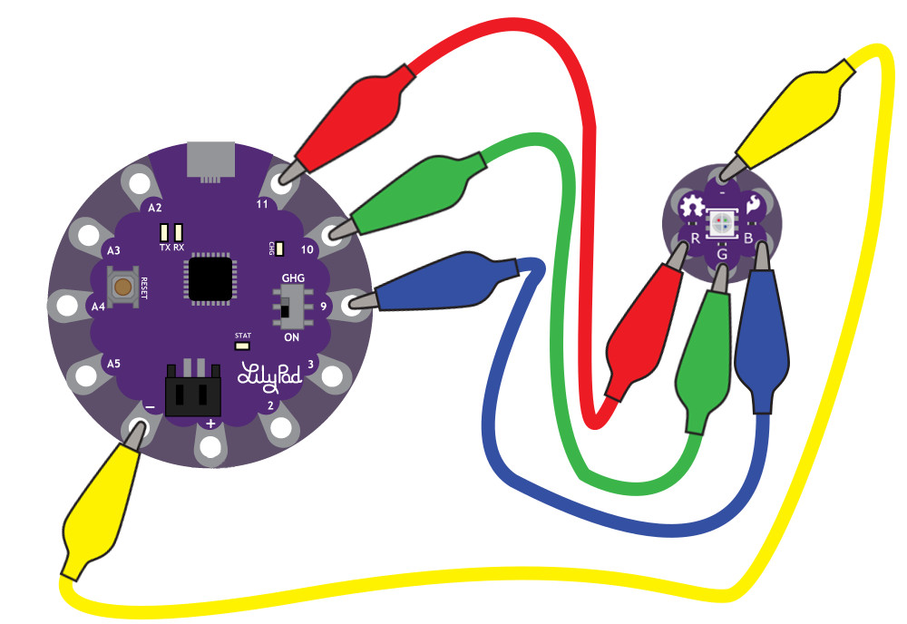
To follow along with the code examples in this tutorial, connect the RGB LED to a LilyPad Arduino as shown below. Use alligator clips to temporarily connect the R (Red) tab on the LED to 11, G (Green) to 10, B (Blue) to 9, and (-) to (-). When you are finished prototyping, replace the alligator clips with conductive thread traces for permanent installation in your project.
Additional Board Hookup
If you'd like to use RGB LED with the LilyPad ProtoSnap Plus, attach the R, G, and B tabs to the ProtoSnap's expansion ports. You will not be able to follow along with the Custom Color Mixing example unless you snap the ProtoSnap Plus apart and connect the RGB LED directly to tabs on the LilyPad USB Plus on pin 6, A7, and A8. Make sure to adjust the pins definitions in the example code when using the LilyPad ProtoSnap Plus.
Basic Color Mixing with Code
Note: This example assumes you are using the latest version of the Arduino IDE on your desktop. If this is your first time using Arduino, please review our tutorial on installing the Arduino IDE.
This example code demonstrates how to display a simple rainbow of colors using the RGB LED. In order to create colors with the RGB LED, you'll have to set each of the LEDs within it individually. The combination of light from the LEDs mixed together creates new colors.
Copy and paste the following code into the Arduino IDE and upload it to your LilyPad Arduino.
language:c
/*
  LilyPad Tri-Color LED: Basic Color Mixing
  Written by: Gella and Ho Yun "Bobby" Chan
  SparkFun Electronics
  https://www.sparkfun.com/products/13735

  Create primary and secondary colors on the tri-color (Red/Green/Blue)
  LED connected to a LilyPad Arduino.

  Tri-Color LED connections:
  R pin to 11
  G pin to 10
  B pin to 9
  - pin to -


  This code is released under the MIT License (http://opensource.org/licenses/MIT)

******************************************************************************/

// This example uses a tri-color, also known as an RGB
// (Red / Green / Blue) LED.
// This example uses digitalWrite() to turn the three LEDs on and off
// in various combinations to create eight primary and secondary colors.

//debug mode, comment one of these lines out using a syntax for a single line comment: //
#define DEBUG 0     //0 = LEDs only
//#define DEBUG 1     //1 = LEDs w/ serial output

// Create integer variables for our LED pins:
#define RGB_red 11
#define RGB_green 10
#define RGB_blue 9

void setup() {

  // Make all of our LED pins outputs:
  pinMode(RGB_red, OUTPUT);
  pinMode(RGB_green, OUTPUT);
  pinMode(RGB_blue, OUTPUT);

#if DEBUG
  Serial.begin(9600); //initialize Serial Monitor
  //while (!Serial);  // Comment out to wait for serial port to connect to Serial Monitor. Needed for native USB.
  Serial.println("Basic Color Mixing w/ a Common Cathode RGB LED");
#endif

}//end setup()

void loop() {

  // This code will step through the six primary and secondary colors, plus white and black.
  // Note: for this particular LED, the wiring shares a common anode (+), which means to
  // turn on the LEDs you will set them LOW instead of HIGH.
  // Keep this in mind as you prototype with the LED and mix your colors.

  // For each of these colors, we'll turn the necessary RGB LEDs on or off.


  // Black (all LEDs off)
  // RGB LEDs:
#if DEBUG
  Serial.println("OFF");
#endif
  digitalWrite(RGB_red, LOW);
  digitalWrite(RGB_green, LOW);
  digitalWrite(RGB_blue, LOW);
  delay(1000);

  // Red (red LED on)
#if DEBUG
  Serial.println("RED");
#endif
  digitalWrite(RGB_red, HIGH);
  digitalWrite(RGB_green, LOW);
  digitalWrite(RGB_blue, LOW);
  delay(1000);

  //Yellow (red and green LEDs on)
#if DEBUG
  Serial.println("YELLOW");
#endif
  digitalWrite(RGB_red, HIGH);
  digitalWrite(RGB_green, HIGH);
  digitalWrite(RGB_blue, LOW);
  delay(1000);

  // Green (green LED on)
#if DEBUG
  Serial.println("GREEN");
#endif
  digitalWrite(RGB_red, LOW);
  digitalWrite(RGB_green, HIGH);
  digitalWrite(RGB_blue, LOW);
  delay(1000);

  // Cyan (blue and green LEDs on)
#if DEBUG
  Serial.println("CYAN");
#endif
  digitalWrite(RGB_red, LOW);
  digitalWrite(RGB_green, HIGH);
  digitalWrite(RGB_blue, HIGH);
  delay(1000);

  // Blue (blue LED on)
#if DEBUG
  Serial.println("BLUE");
#endif
  digitalWrite(RGB_red, LOW);
  digitalWrite(RGB_green, LOW);
  digitalWrite(RGB_blue, HIGH);
  delay(1000);

  // Magenta (red and blue LEDs on)
#if DEBUG
  Serial.println("MAGENTA");
#endif
  digitalWrite(RGB_red, HIGH);
  digitalWrite(RGB_green, LOW);
  digitalWrite(RGB_blue, HIGH);
  delay(1000);

  // White (all LEDs on)
#if DEBUG
  Serial.println("WHITE");
#endif
  digitalWrite(RGB_red, HIGH);
  digitalWrite(RGB_green, HIGH);
  digitalWrite(RGB_blue, HIGH);
  delay(1000);

}//end loop
After uploading your code, the RGB LED will step through a color sequence beginning with all LEDs off ('black'), red, yellow, green, cyan, blue, magenta, and white. Once the color sequence is complete, the program will loop back to the beginning and repeat the sequence.
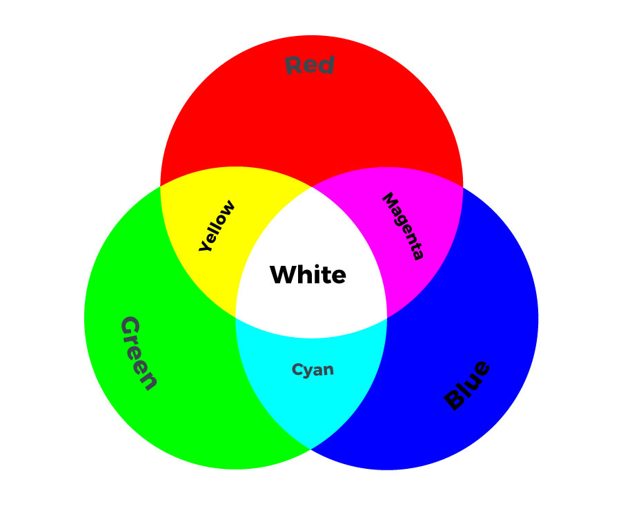
Turning on different combinations of three LEDs inside the RGB LED will create new colors. Combining the primary colors of light (red, green, and blue) gives different results than combining pigments in paints or inks. Turning on all three colors will create white - this is called additive color. Take a look a the graphic below to see what colors combine to create primary and secondary colors with light.
Custom Color Mixing with Code
In this example, you will but use analogWrite() function to change the brightness of each channel in relation to each other. Adjusting the brightness of the red, green, and blue LEDs within the LED will allow you to create a new range of values and color combinations. You will need to confirm that the sew tabs you connect to the RGB LED have PWM capabilities - this code will run on a LilyPad Arduino USB, LilyPad Arduino Simple, LilyPad Arduino SimpleSnap, and LilyPad Main board without any changes needed.
In the last example, you created basic primary and secondary colors by turning the red, green, and blue channels on or off with different combinations. In this activity, you'll create tertiary colors by combining the three color channels at 50% brightness levels. There are actually millions of color combinations available using RGB LEDs once you begin experimenting by adjusting the brightness/saturation of each channel. This example will cover a set of twelve tertiary colors and white.
Copy and paste the following code into the Arduino IDE and upload to your LilyPad Arduino.
language:c
/*
  LilyPad RGB LED: Custom Color Mixing
  Written by: Gella and Ho Yun "Bobby" Chan
  SparkFun Electronics
  https://www.sparkfun.com/products/13735

  Expand your color options using analogWrite and the LilyPad RGB LED

  RGB LED connections:
  R pin to 11
  G pin to 10
  B pin to 9
  - pin to -

  This code is released under the MIT License (http://opensource.org/licenses/MIT)

******************************************************************************/
// In this example we'll use analogWrite to control the brightness of the three channels
// of the RGB LED.
// Here we'll create a rainbow of tertiary colors by adding a 50%-brightness option.

//debug mode, comment one of these lines out using a syntax for a single line comment: //
//#define DEBUG 0     //0 = LEDs only
#define DEBUG 1     //1 = LEDs w/ serial output

// Create integer variables for our LED pins:
#define RGB_red 11
#define RGB_green 10
#define RGB_blue 9

void setup() {

  // Make all of our LED pins outputs:
  pinMode(RGB_red, OUTPUT);
  pinMode(RGB_green, OUTPUT);
  pinMode(RGB_blue, OUTPUT);

#if DEBUG
  Serial.begin(9600); //initialize Serial Monitor
  //while (!Serial); // Comment out to wait for serial port to connect to Serial Monitor. Needed for native USB.
  Serial.println("Custom Color Mixing w/ a Common Cathode RGB LED");
#endif

}//end setup()

void loop()
{
  // In this code we'll step through twelve rainbow colors (primary, secondary, tertiary).

  // Unlike digitalWrite, which can be only HIGH (on) or LOW (off),
  // analogWrite lets you smoothly change the brightness from 0 (off) to 255 (fully on).
  // When analogWrite is used with the RGB LED, you can create millions of colors!

  // In the analogWrite() functions:
  // 0 is off
  // 128 is halfway on (used for the tertiary colors)
  // 255 is full brightness.

  // Black (all LEDs off)
  // RGB LEDs:
#if DEBUG
  Serial.println("OFF");
#endif
  analogWrite(RGB_red, 0);
  analogWrite(RGB_green, 0);
  analogWrite(RGB_blue, 0);
  delay(1000);

  // Red
#if DEBUG
  Serial.println("RED");
#endif
  analogWrite(RGB_red, 255);
  analogWrite(RGB_green, 0);
  analogWrite(RGB_blue, 0);
  delay(1000);

  // Orange
#if DEBUG
  Serial.println("ORANGE");
#endif
  analogWrite(RGB_red, 255);
  analogWrite(RGB_green, 128);
  analogWrite(RGB_blue, 0);
  delay(1000);

  // Yellow
#if DEBUG
  Serial.println("YELLOW");
#endif
  analogWrite(RGB_red, 255);
  analogWrite(RGB_green, 255);
  analogWrite(RGB_blue, 0);
  delay(1000);

  // Chartruese
#if DEBUG
  Serial.println("CHARTRUESE");
#endif
  analogWrite(RGB_red, 128);
  analogWrite(RGB_green, 255);
  analogWrite(RGB_blue, 0);
  delay(1000);

  // Green
#if DEBUG
  Serial.println("GREEN");
#endif
  analogWrite(RGB_red, 0);
  analogWrite(RGB_green, 255);
  analogWrite(RGB_blue, 0);
  delay(1000);

  // Spring Green
#if DEBUG
  Serial.println("SPRING GREEN");
#endif
  analogWrite(RGB_red, 0);
  analogWrite(RGB_green, 255);
  analogWrite(RGB_blue, 128);
  delay(1000);

  // Cyan
#if DEBUG
  Serial.println("CYAN");
#endif
  analogWrite(RGB_red, 0);
  analogWrite(RGB_green, 255);
  analogWrite(RGB_blue, 255);
  delay(1000);

  // Azure
#if DEBUG
  Serial.println("AZURE");
#endif
  analogWrite(RGB_red, 0);
  analogWrite(RGB_green, 128);
  analogWrite(RGB_blue, 255);
  delay(1000);

  // Blue
#if DEBUG
  Serial.println("BLUE");
#endif
  analogWrite(RGB_red, 0);
  analogWrite(RGB_green, 0);
  analogWrite(RGB_blue, 255);
  delay(1000);

  // Violet
#if DEBUG
  Serial.println("VIOLET");
#endif
  analogWrite(RGB_red, 128);
  analogWrite(RGB_green, 0);
  analogWrite(RGB_blue, 255);
  delay(1000);

  // Magenta
#if DEBUG
  Serial.println("MAGENTA");
#endif
  analogWrite(RGB_red, 255);
  analogWrite(RGB_green, 0);
  analogWrite(RGB_blue, 255);
  delay(1000);

  // Rose
#if DEBUG
  Serial.println("ROSE");
#endif
  analogWrite(RGB_red, 255);
  analogWrite(RGB_green, 0);
  analogWrite(RGB_blue, 128);
  delay(1000);

  // White (all LEDs on)
#if DEBUG
  Serial.println("ALL ON, WHITE");
#endif
  analogWrite(RGB_red, 255);
  analogWrite(RGB_green, 255);
  analogWrite(RGB_blue, 255);
  delay(1000);
}//end loop
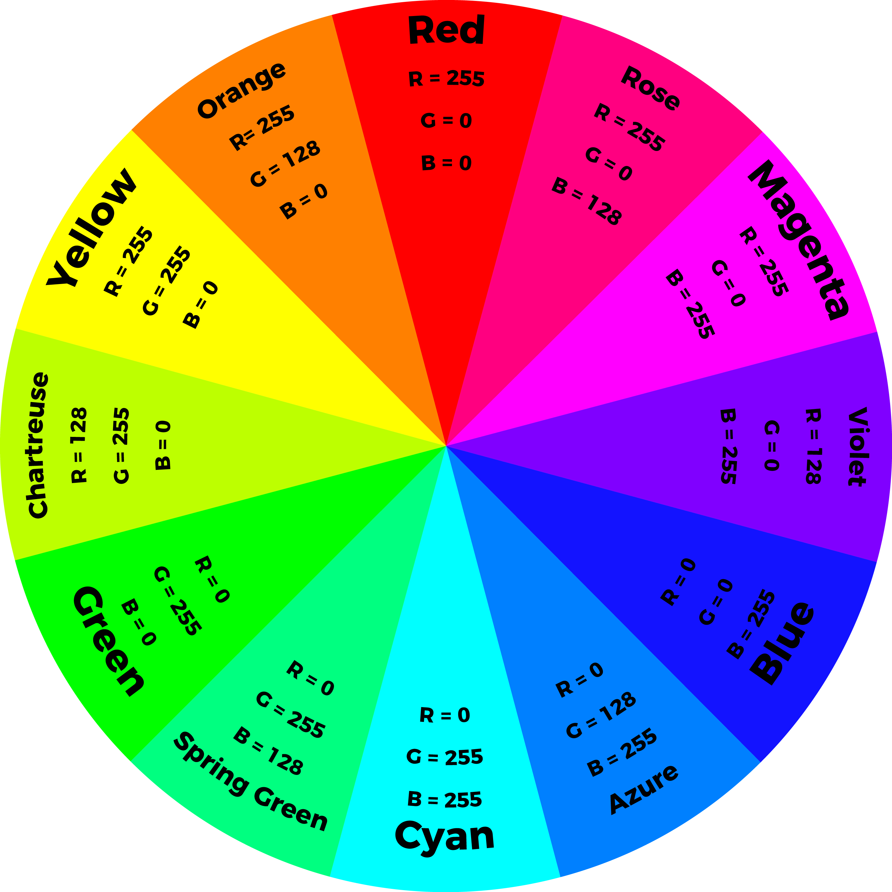
After uploading your code the RGB LED will step through a rainbow sequence of red, orange, yellow, chartruese, green, spring green, cyan, azure, blue, violet, magenta, rose, and white repeatedly.
By adjusting the brightness of each LED in the RGB LED individually, we open up a much wider range of color options to display than the previous example. In fact, there are many more combinations than we show in the example code. The image below shows a chart of the tertiary colors the example program creates by stepping down the LEDs to half brightness, creating a rainbow with more color transitions than the Basic Color Mixing example. By using analog output to adjust the brightness of each color channel individually, the RGB LED can display almost any color you can choose from a color picker - if you are familiar with RGB sliders in a graphics program, you'll recognize the 0-255 values used in this code.
Project Examples
Need some inspiration for your next project? Check out some of the projects below. Just make sure to adjust the connections when using the common cathode RGB LED.
Light Up Silk Flower Corsage
This tutorial uses a specialty Silk Flower LED with embedded RGB LED in it, but functions similar to the example circuit above. You can create a similar project using an RGB LED and your own flower or fabric covering.
Light Up Silk Flower Corsage
April 20, 2015
Color Changing LED Brooch by Becky Stern
In this project for Craftzine, Becky uses three potentiometers to make a customizable colored LED brooch using the RGB LED.
Skirt Full of Stars by Shannon Henry
This skirt reacts to movement and displays in color with RGB LEDs and fiber optic strands. It uses a LilyPad Accelerometer connected to a LilyPad Arduino Main Board to sense movement while being worn.

Resources and Going Further
Now that you've successfully got your LilyPad Tri-Color LED up and running, it's time to incorporate it into your own project! For more information about the LilyPad Tri-Color LED, check out the resources below:
Check out these other tutorials using RGB LEDs:
Hackers in Residence - Sound and Motion Reactivity for Wearables
Humidity-sensing LED Flower
Light Up Silk Flower Corsage
LED Cloud-Connected Cloud
Learn more about working with LilyPad LEDs in your projects: