LED PomPom Headbands
 Feldi
Feldi 
Advanced PomPom Headband
STEP 1:
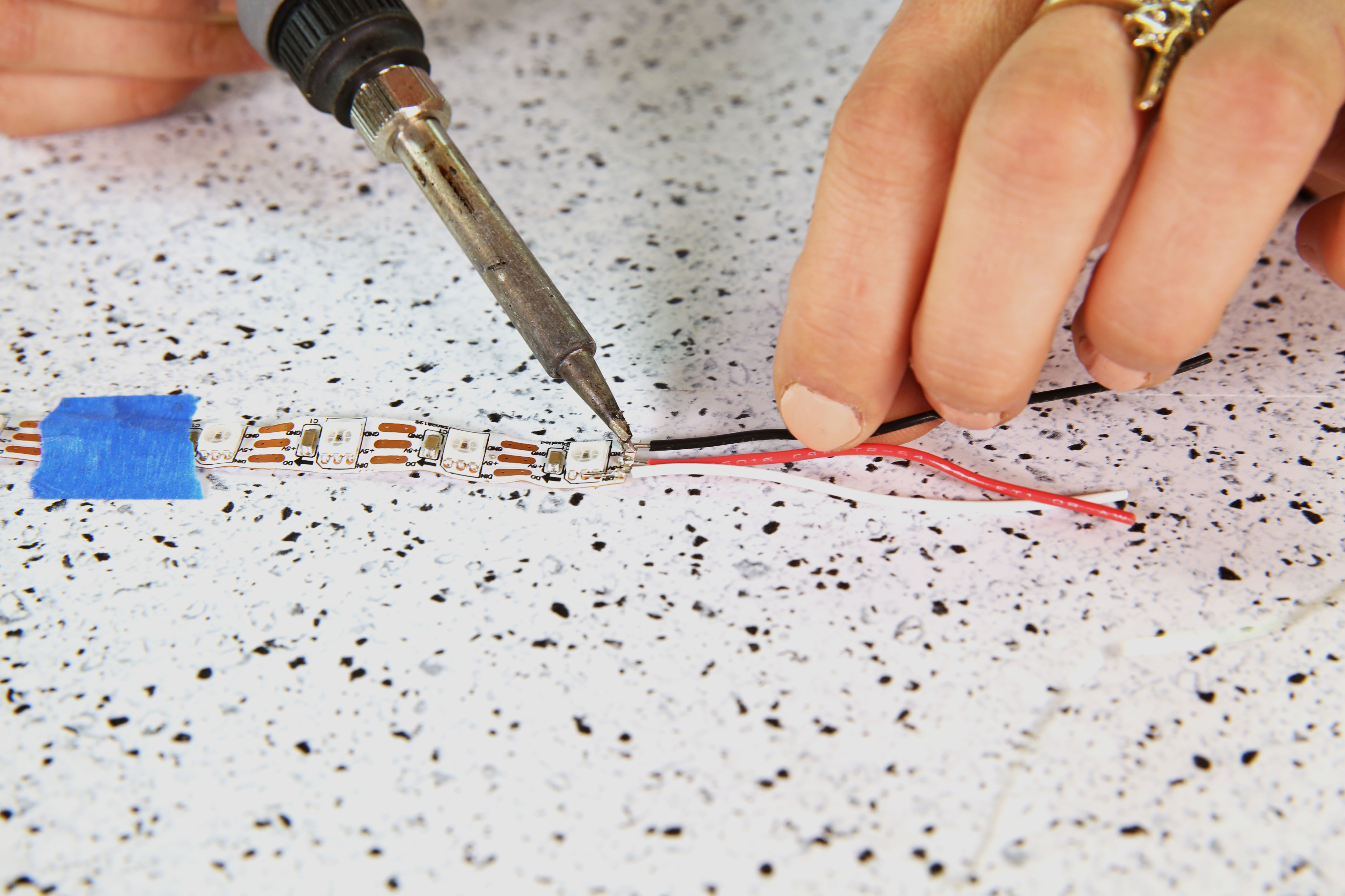
Cut your addressable LED strip down so that you have 10x LEDs on one strip. Cut three strands of hookup wire and strip them using a wire stripper. Solder the hook up wire leads to the solder pads on the LED strip. Feel free to use some tape to help hold down the LED strip when soldering the wires. Make sure you are on the end that says DIN and not DOUT. We will be using these leads again in step 7.
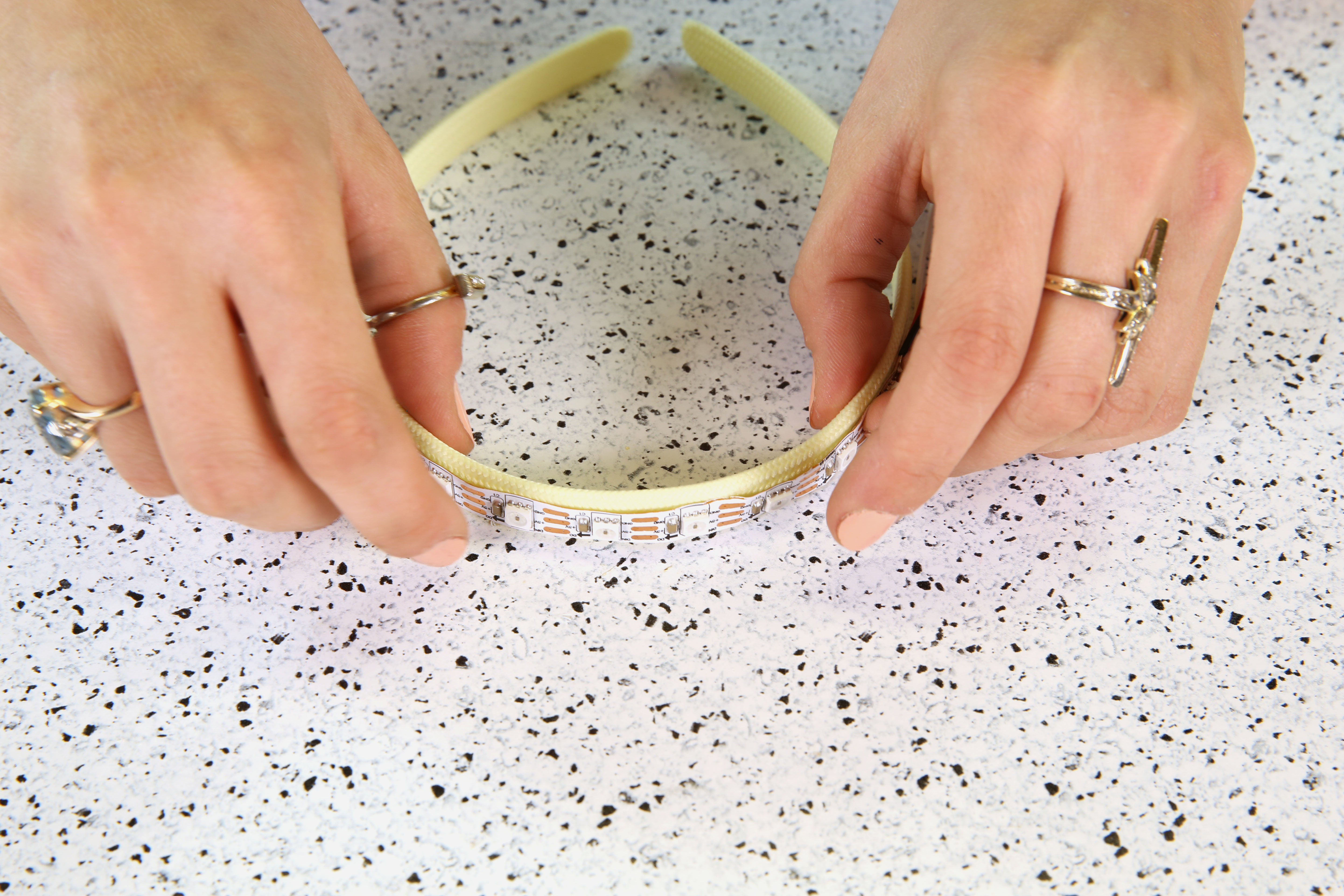
STEP 2:
Add hot glue to the back of the LED strip.
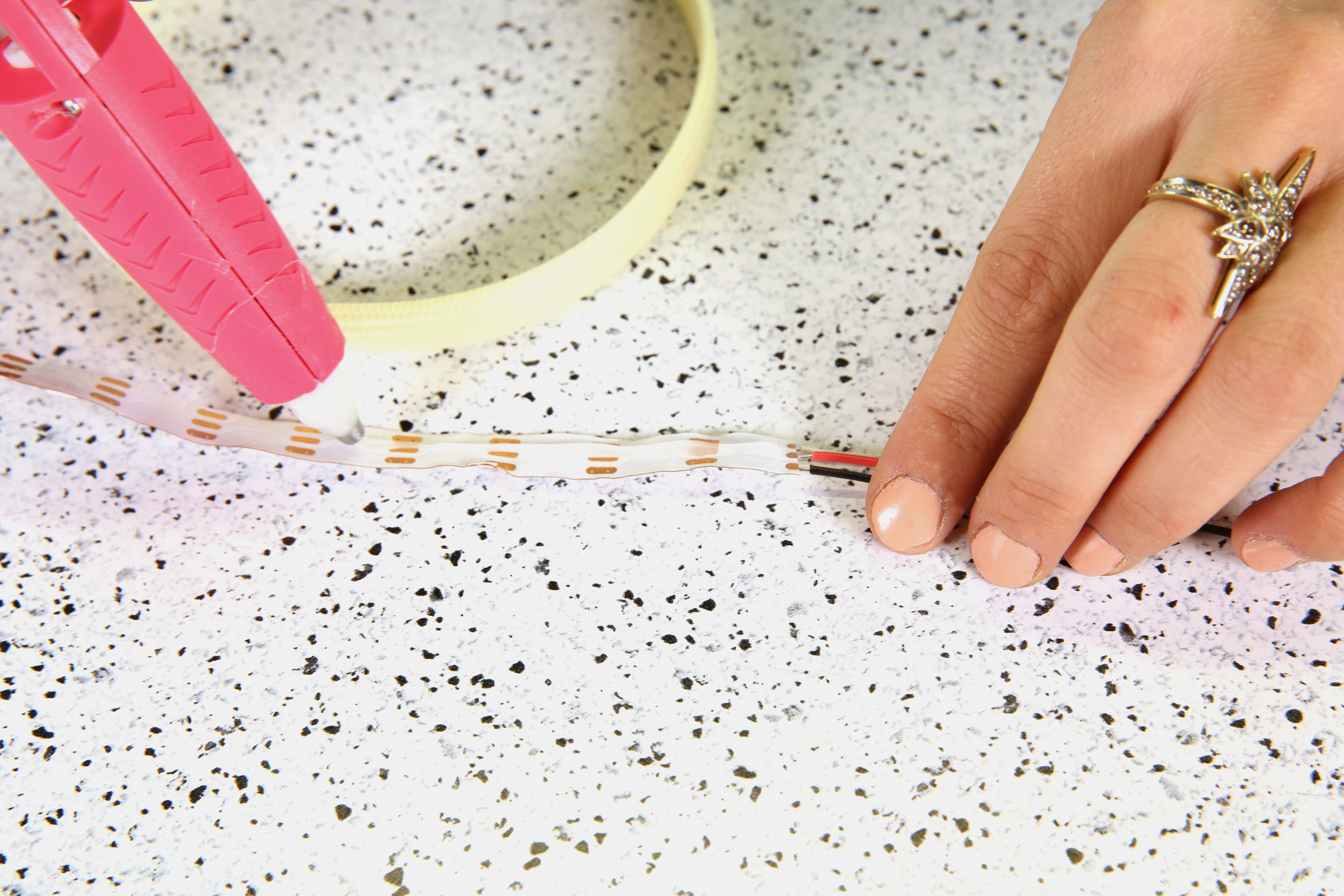
Attach the LED strip to the top of the headband before the hot glue cools down and make sure to center it as much as possible. Set aside when complete.
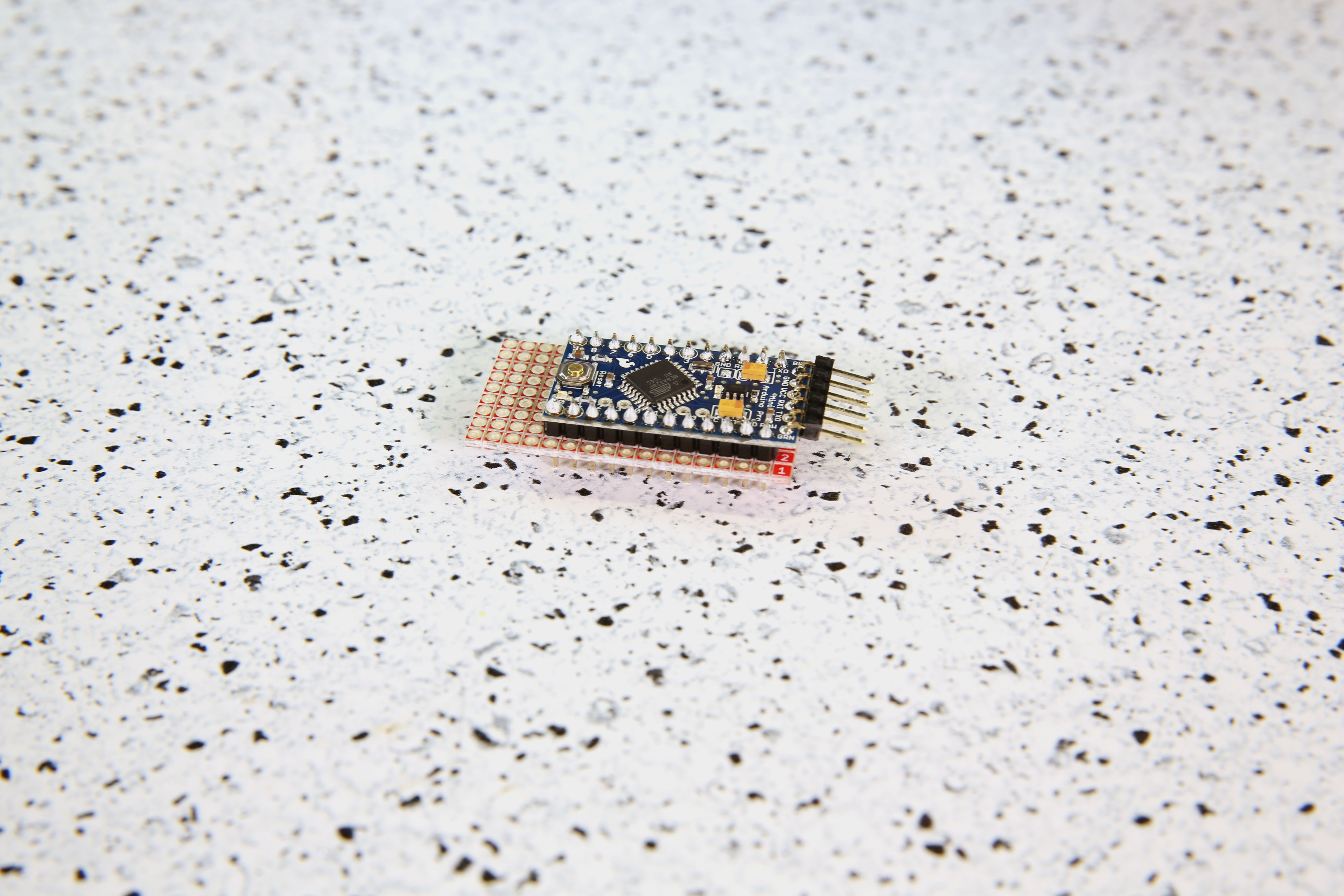
STEP 3:
Prepare your Arduino Pro Mini by soldering headers to the plated through holes. Solder right angle headers to the FTDI headers at the top of the board (short side), and straight headers to plated through holes on the sides of the board (longer side).

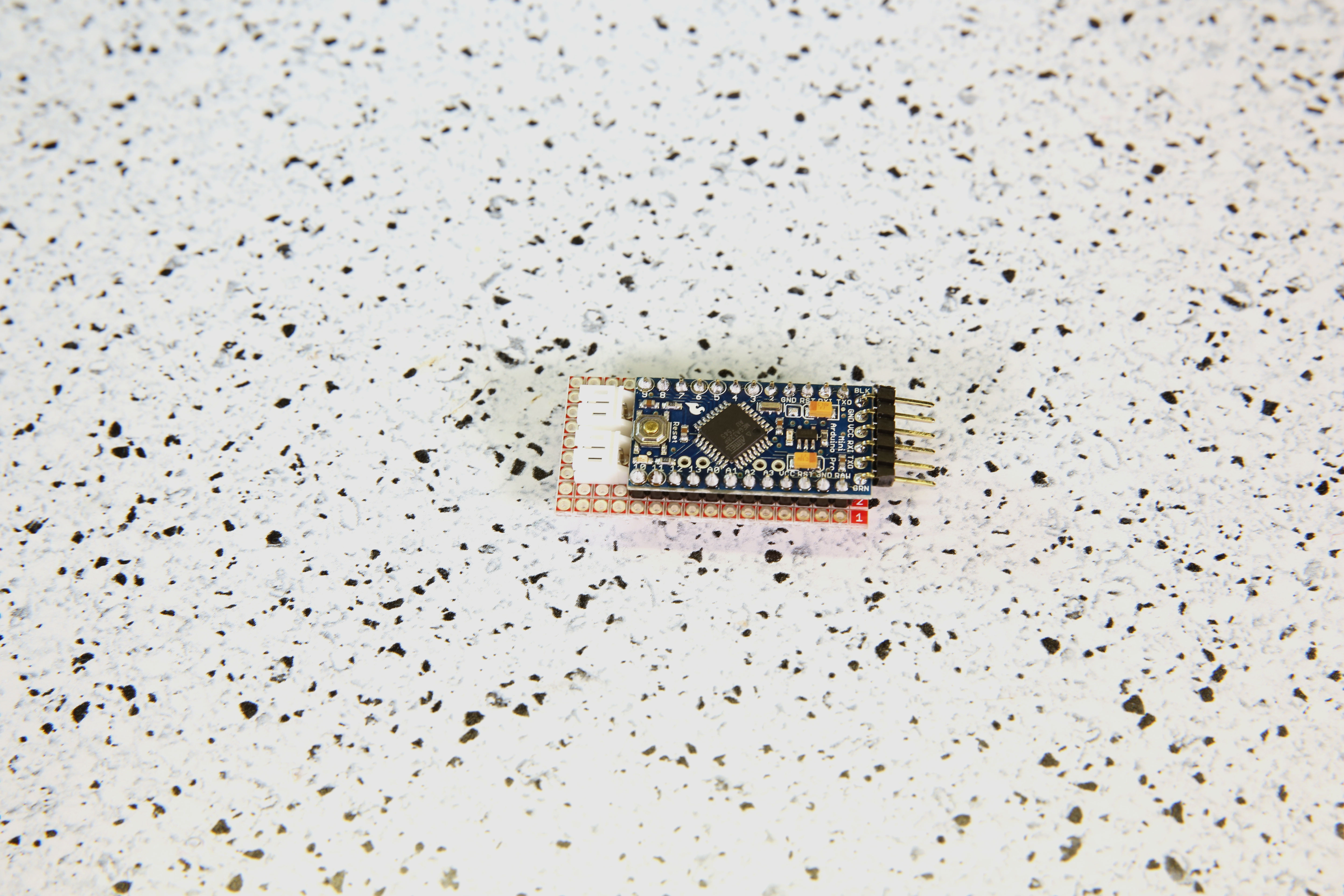
STEP 4:
Break off a grid of 9x16 from the snappable protoboard. Solder your Arduino to it. Ensure that it is positioned so that there is one row of protoboard available on each side, and space for the programming headers.
STEP 5:
Add 2x JST connectors wired parallel using hook up wire. This means that you will need to connect the Arduino's Vcc pin to the red wire of BOTH batteries and the GND pin to the black wires of BOTH batteries. As a result, you will have a capacity of 800mAh for your power source. If you have an 800mAH battery or above, you only need one JST connector.
*PLEASE NOTE: In order to connect two batteries in parallel, they MUST be the same voltage. While not reflected in these images, you can also add a Schottky diode in series for each LiPo battery for extra protection.
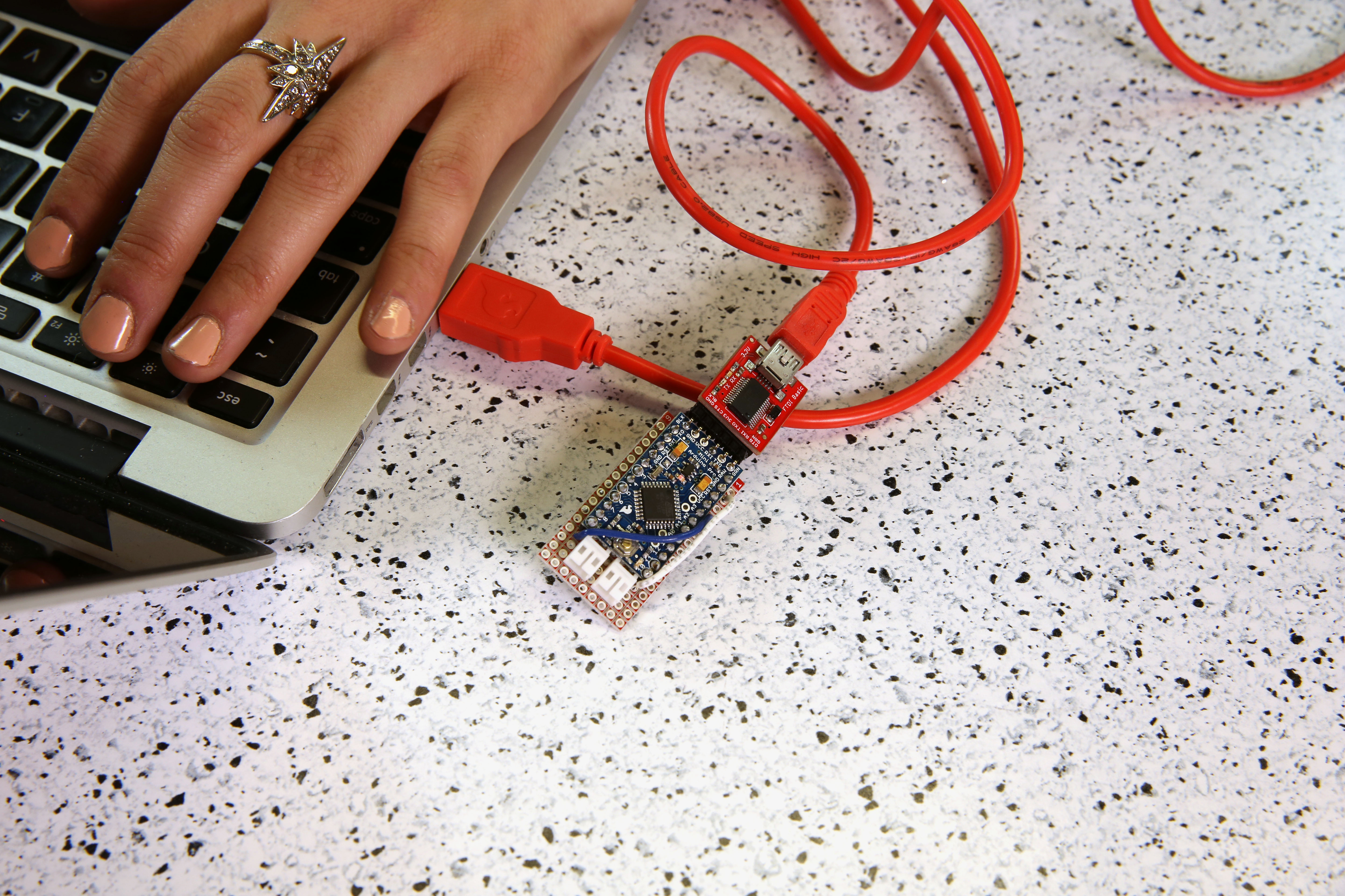
Step 6:
Before programming your Arduino, make sure to connect the 5V Arduino Pro Mini, 5V FTDI, and USB cable to your computer.
In order for this example code to work, you will need to install the Adafruit Neopixel Library. For Arduino IDE users, click here to download a copy of the NeoPixel library along with some example code SparkFun has created.
If you are unfamiliar with uploading a program to your Arduino or the library installation process, please visit this tutorial on installing and using the Arduino IDE, and this tutorial on installing Arduino Libraries.
Program your Arduino by uploading the example code provided below.
language:c
//PomPom headband by Melissa Felderman for SparkFun
//This sketch is an edited version of the Adafruit Neopixel Strand Test example code from the Neopixel Library.

#include <Adafruit_NeoPixel.h>
#ifdef __AVR__
  #include <avr/power.h>
#endif

#define PIN 2


Adafruit_NeoPixel strip = Adafruit_NeoPixel(10, PIN, NEO_GRB + NEO_KHZ800);


void setup() {
  // This is for Trinket 5V 16MHz, you can remove these three lines if you are not using a Trinket
  #if defined (__AVR_ATtiny85__)
    if (F_CPU == 16000000) clock_prescale_set(clock_div_1);
  #endif
  // End of trinket special code


  strip.begin();
  strip.show(); // Initialize all pixels to 'off'
}

void loop() {

  rainbowCycle(20);

}


// Slightly different, this makes the rainbow equally distributed throughout
void rainbowCycle(uint8_t wait) {
  uint16_t i, j;

  for(j=0; j<256*5; j++) { // 5 cycles of all colors on wheel
    for(i=0; i< strip.numPixels(); i++) {
      strip.setPixelColor(i, Wheel(((i * 256 / strip.numPixels()) + j) & 255));
    }
    strip.show();
    delay(wait);
  }
}


// Input a value 0 to 255 to get a color value.
// The colours are a transition r - g - b - back to r.
uint32_t Wheel(byte WheelPos) {
  WheelPos = 255 - WheelPos;
  if(WheelPos < 85) {
    return strip.Color(255 - WheelPos * 3, 0, WheelPos * 3);
  }
  if(WheelPos < 170) {
    WheelPos -= 85;
    return strip.Color(0, WheelPos * 3, 255 - WheelPos * 3);
  }
  WheelPos -= 170;
  return strip.Color(WheelPos * 3, 255 - WheelPos * 3, 0);
}
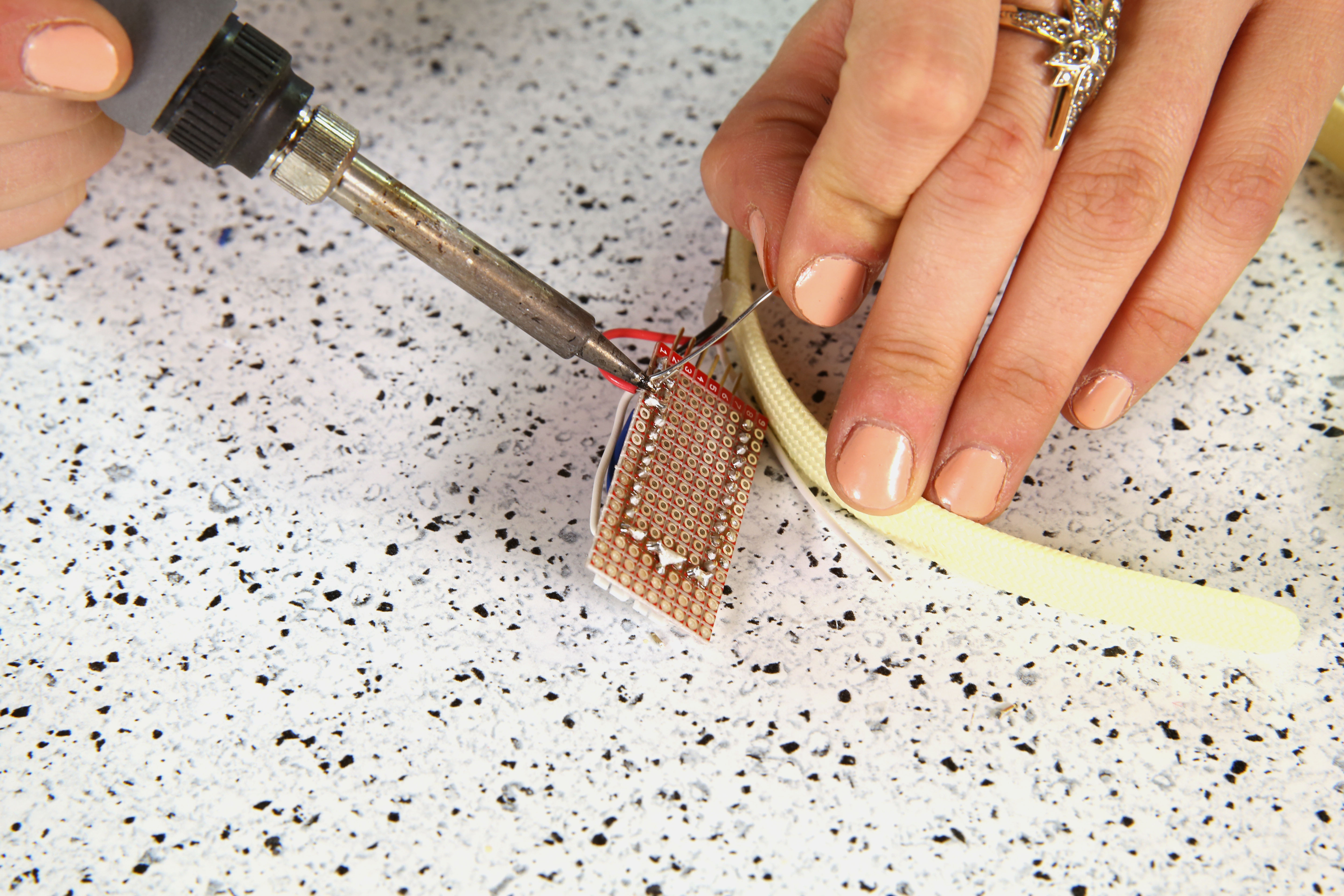
STEP 7:
Find the hook up wire leads we attached to the LED strip in Step 1. Solder the DIN lead from the LED strip to pin 2 on your Arduino, GND to GND, and VCC to VCC. Since the snappable protoboards do not have metal traces connecting the pins together, you will need to add a solder bridge (similar to this example) between the holes to complete each connection.
STEP 8:
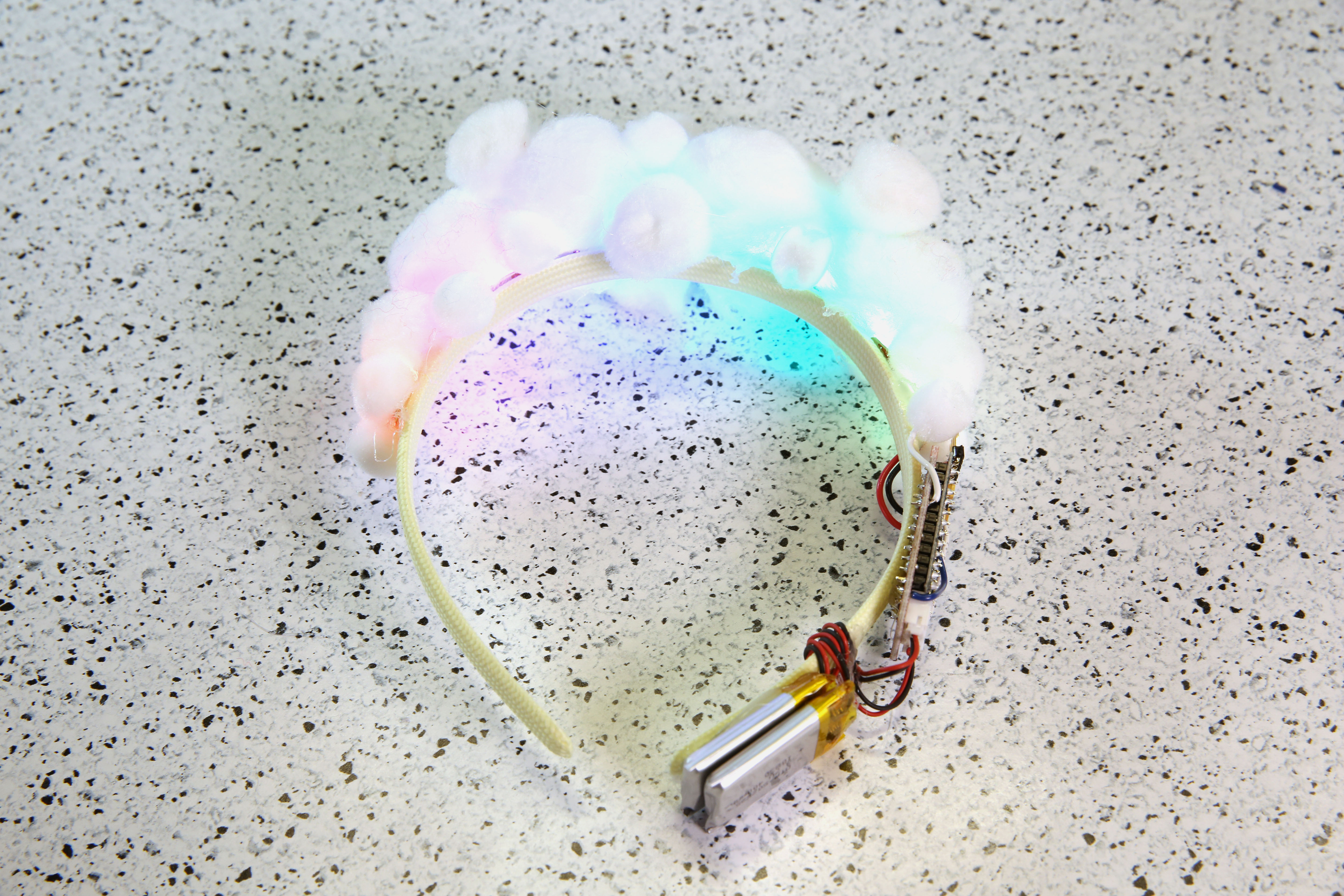
Test your circuit! Make sure that your circuit is working properly and lighting up before moving on to the next step. To test, plug in the LiPo battery into the circuit. If you used the provided code, your LEDs should animate with a rainbow spectrum that slowly flows from color to color.
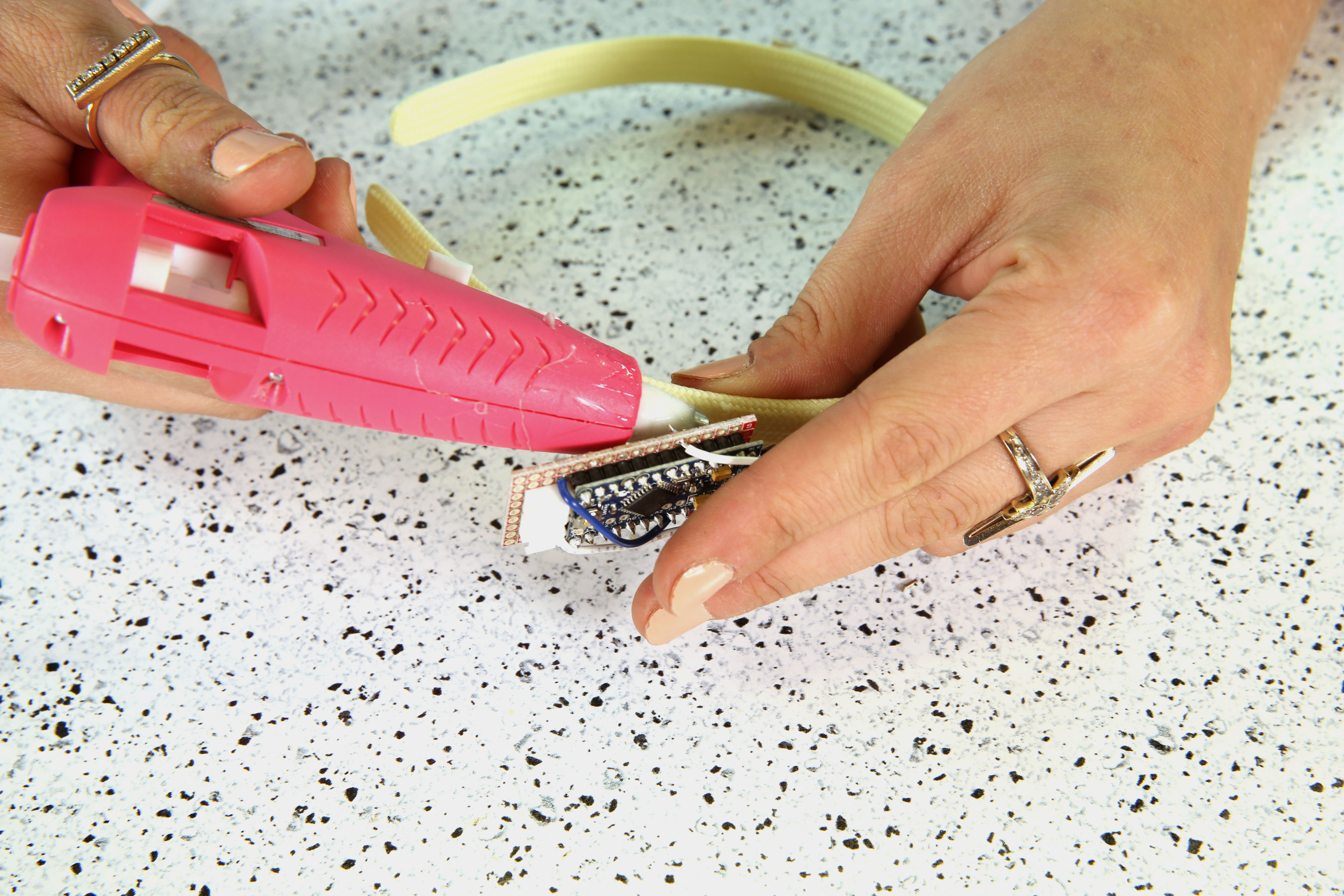
STEP 9:
Glue down the back of the circuit to your headband as shown in the image below.
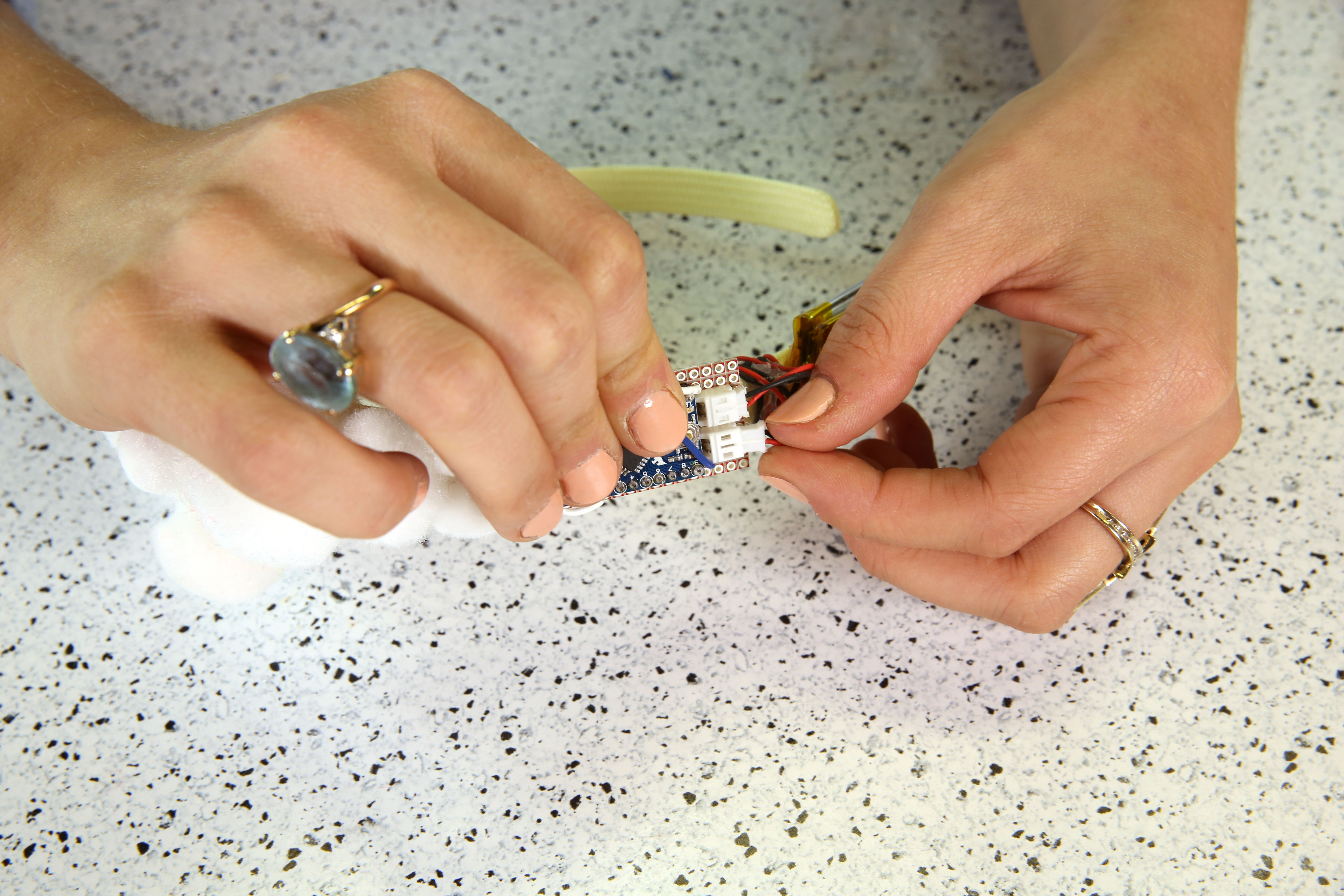
STEP 10:
On the same side, add double stick tape to your battery on the very bottom and attach to the headband. Wrap the wires around the headband to secure the wires. Add an additional drop of glue to hold the wires down against the headband.
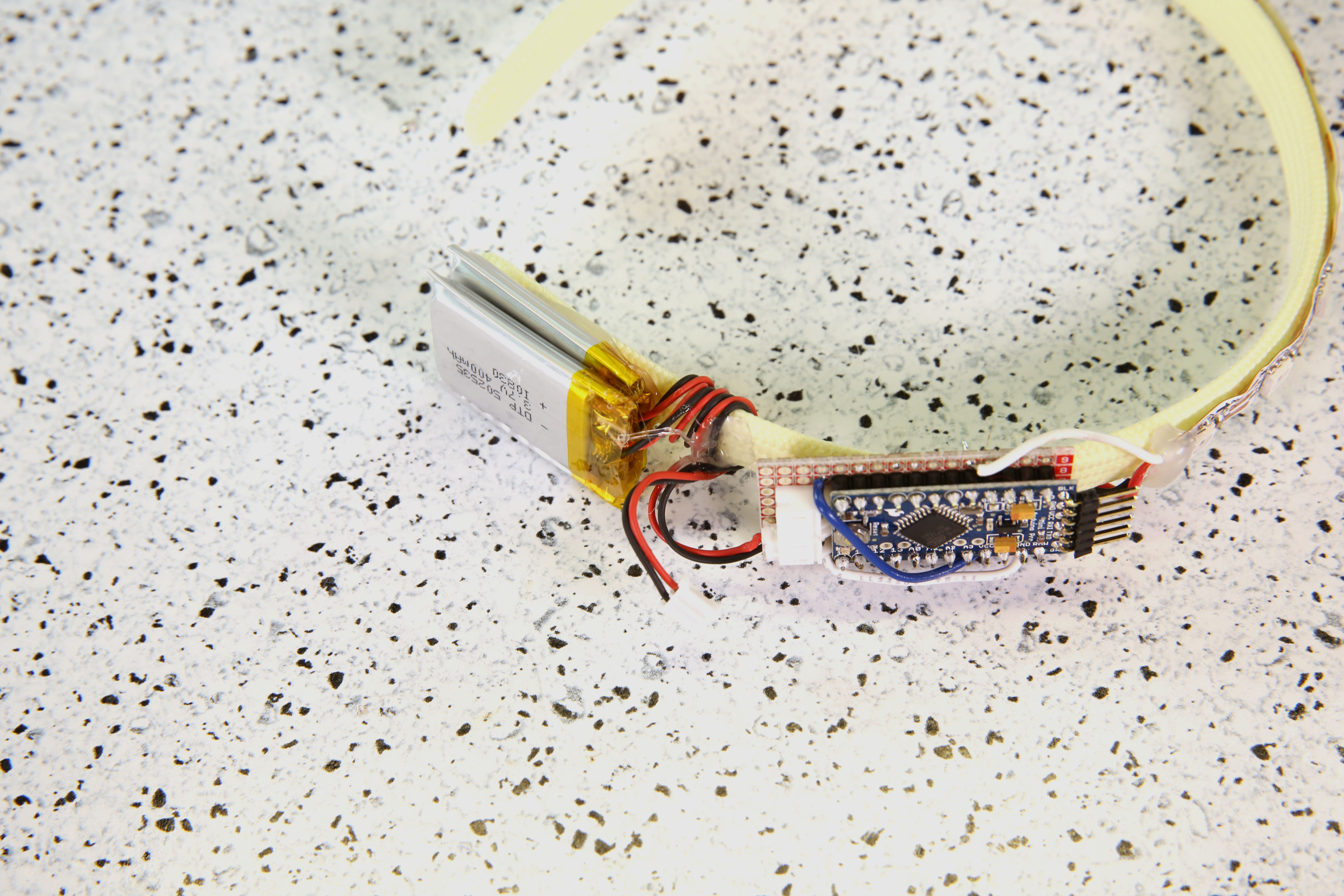
*PLEASE NOTE: It is never a good idea to apply heat to a LiPo battery using a hot glue gun. A safer solution is to secure the battery with some thread or tape.
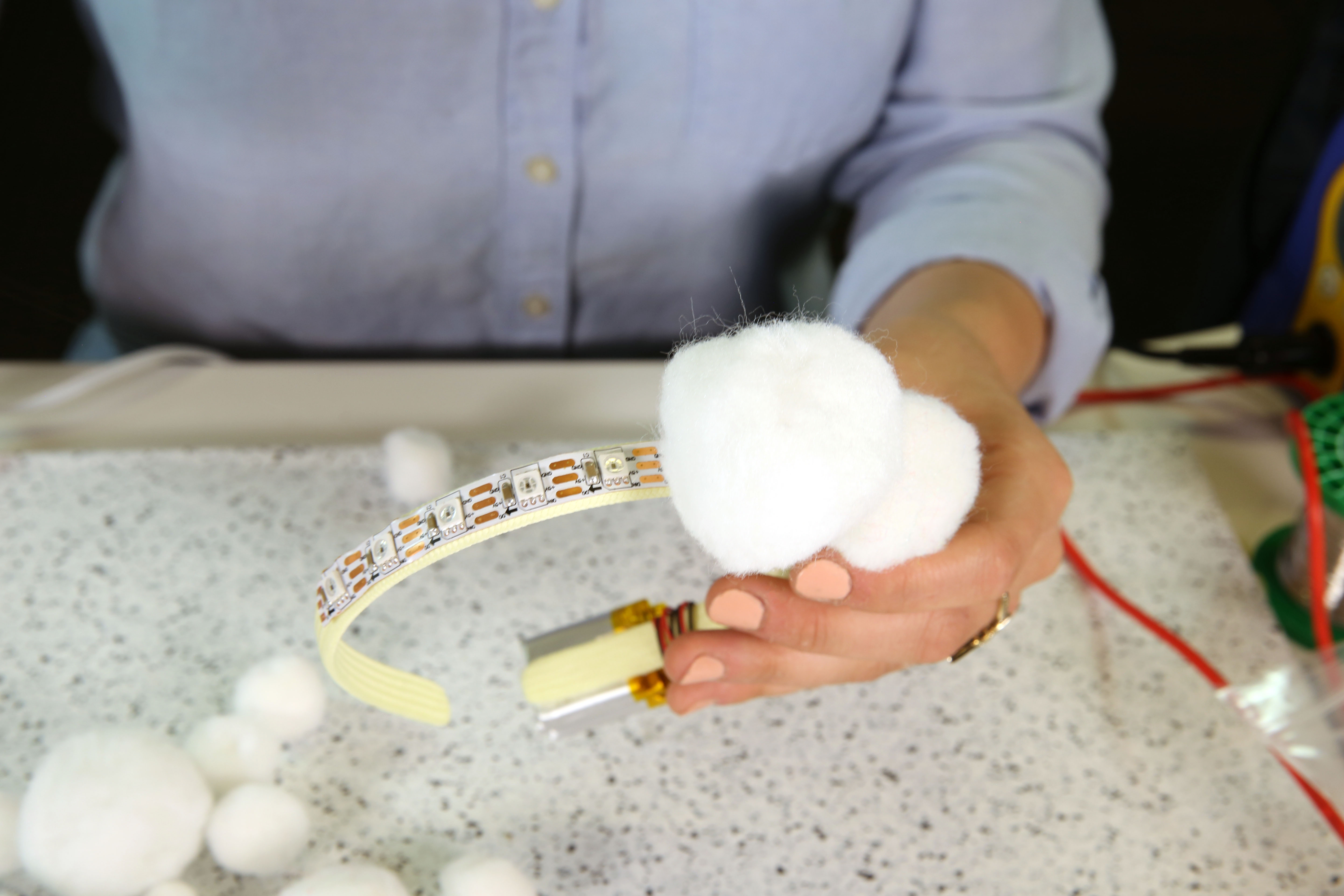
STEP 11:
Glue white PomPoms directly on top of the area covered by the LED strip.
STEP 12:
Plug in and enjoy!