IOTA (ARTIC R2) Satellite Communication Module Hookup Guide
 PaulZC
Hardware Overview
In this section we'll cover what's included on the IOTA (ARTIC R2) Satellite Communication Module.
ARTIC R2
The heart of IOTA is, of course, the ARTIC R2 transceiver itself. This is a clever chip containing a Digital Signal Processor (DSP) which modulates transmit messages and demodulates received messages. The DSP can boot from on-board flash memory or from an external microcontroller via SPI. When transmitting, it produces a 1mW (0dBm) output signal which is fed to a separate power amplifier.
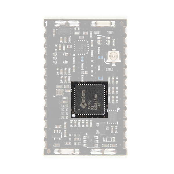
Our Arduino Library does all of the heavy lifting for you. By default, the library will tell the ARTIC R2 DSP to boot from the on-board flash memory. However, by changing one line of code, you can instead boot via SPI with your microcontroller providing the firmware for the DSP.
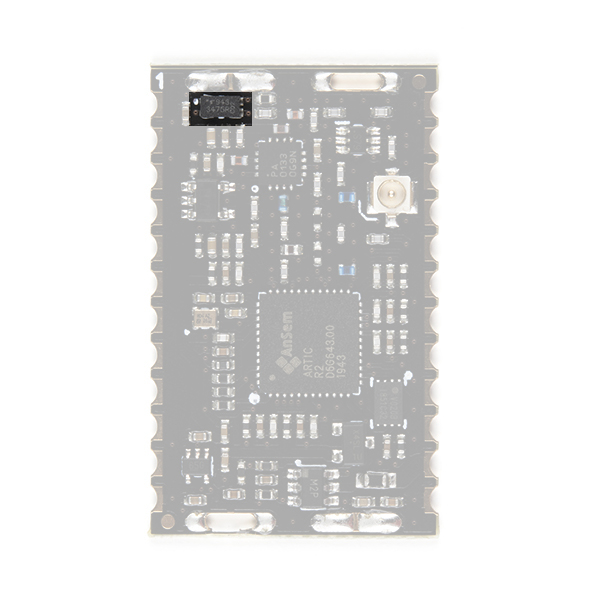
RF Amplifier
During transmit, the RFPA0133 power amplifier boosts the 0dBm (1mW) signal from the ARTIC R2.
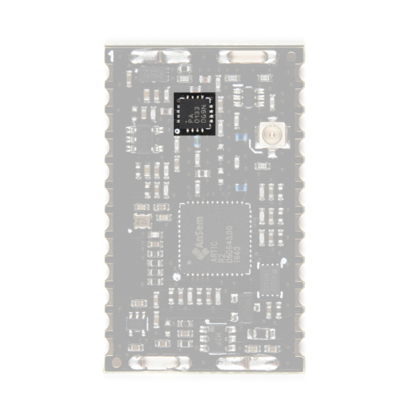
Using full gain, the amplifier boosts the signal to approximately 25.7dBm (370mW). If you are using ARGOS 2 or 3 modulation and are transmitting from a 'noisy' environment, like a city, then you are probably going to need to use full power to ensure your messages get through. However, if you are using ARGOS 4 modulation and/or are transmitting from a 'quiet' environment, like the tundra or the ocean, then you will be able to transmit at reduced power.
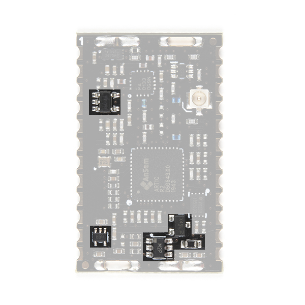
Gain Control
You can adjust the transmit gain through software and the on-board opto-isolated gain control circuit.
Our Arduino Library can reduce the gain for you. If you call:
language:c
myARTIC.attenuateTXgain(true);
from inside your code, the opto-isolator will pull the RFPA0133's G8 pin low, reducing the gain by approximately 5dB. This also has the advantage of reducing the transmit current by approximately 80mA.
Flash Memory
By default, the DSP inside the ARTIC R2 will boot from the on-board flash memory. (But, as mentioned above, you also have the option of booting via SPI.)
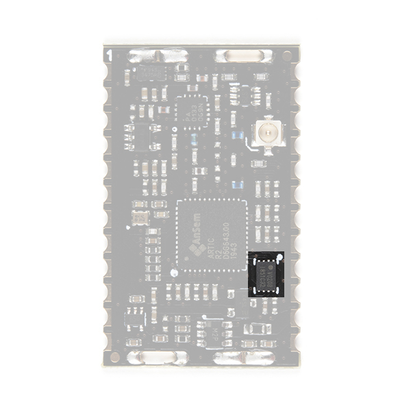
During production testing at SparkFun, we program the flash memory with the ARTIC R2 firmware (ARTIC006) and a Platform ID allocated by CLS. You will need to register the Platform ID on your ARGOS account to activate it. The Arduino Library reads the Platform ID from memory and uses it in the transmissions.
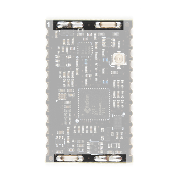
Antenna
On IOTA, you have a choice of antenna connection: u.FL; or a castellated pad.
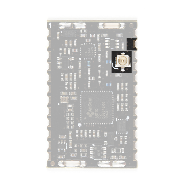
Check out our tutorial if you haven't used u.FL before:
Three Quick Tips About Using U.FL
Power Circuit
The IOTA requires a 3.3V ±0.1V DC power supply able to cope with the maximum transmit current of 230mA.
The power circuit comprises: in-rush and over-current protection; 3.0V and 1.8V regulators.
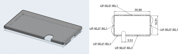
Screening Can
IOTA has slots and ground pads for an RF screening can, should your certification process require one.
You can find the design for the screening can on onshape. You can right-click on the onshape document tabs and select Export... to export the design in a variety of formats.