IOTA (ARTIC R2) Satellite Communication Module Hookup Guide
Contributors:
 PaulZC
PaulZC 
Castellated Pads
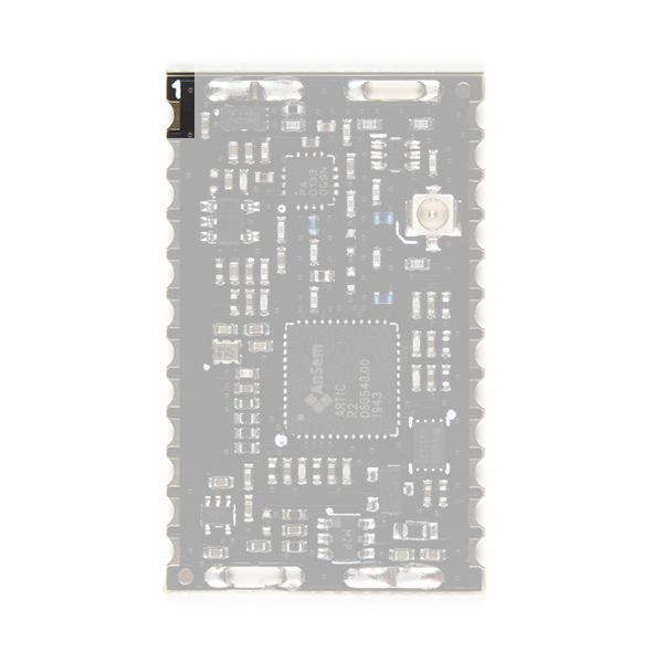
The IOTA has 24 castellated pads. It can be reflowed or hand-soldered onto a PCB depending on your needs.
You will find an Eagle symbol and footprint for IOTA in the SparkFun Eagle Libraries RF Library.
The photo below shows the bottom of IOTA. Pad 1 is top right.
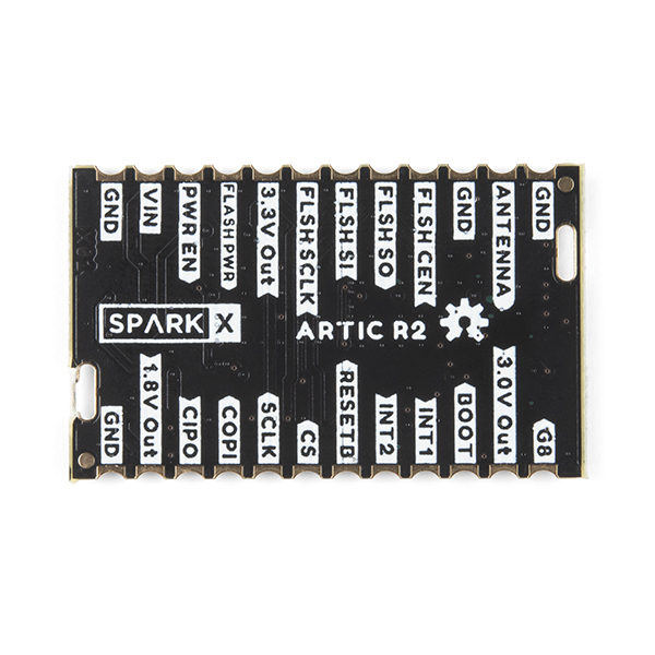
The table below describes the function of each of the IOTA's castellated pads. Looking at IOTA from the top, pad 1 is top left. Pad numbering is counter-clockwise.
| Pad No. | Name | Function | Description | |
|---|---|---|---|---|
| 1 | G8 | INPUT | Pull up to 3.3V to set the RFPA0133 transmit power to maximum. The transmit power will be reduced by _approximately_ 5dB if this pin is pulled low or left open. | |
| 2 | 3.0V Out | OUTPUT | This pad allows measurement of the module's internal 3.0V rail. | |
| 3 | BOOT | INPUT | Connected to the ARTIC BOOT pin. Pulled up to 3.3V via a 100k resistor. When high, the ARTIC boots from the external flash memory. Pull low if the ARTIC firmware will be downloaded by the MCU via SPI. | |
| 4 | INT1 | OUTPUT | Connected to the ARTIC INT1 pin. Will be pulled up to 3.3V by the ARTIC to indicate (e.g.) an RX_VALID_MESSAGE. | |
| 5 | INT2 | OUTPUT | Connected to the ARTIC INT2 pin. Will be pulled up to 3.3V by the ARTIC to indicate (e.g.) an RX_BUFFER_OVERFLOW. | |
| 6 | RESETB | INPUT | Connected to the ARTIC reset pin. Pulled up to 3.3V via a 100k resistor. Pull low to reset the ARTIC. | |
| 7 | CS | INPUT | SPI interface Chip Select. 3.3V. Active low. | |
| 8 | SCLK | INPUT | SPI interface clock signal. Typically 1MHz. 3.3V. See the ARTIC R2 datasheet for the permitted clock speeds. | |
| 9 | COPI | INPUT | SPI interface: Controller Out Peripheral In. 3.3V. | |
| 10 | CIPO | OUTPUT | SPI interface: Controller In Peripheral Out. 3.3V. | |
| 11 | 1.8V Out | OUTPUT | This pad allows measurement of the module's internal 1.8V rail. | |
| 12 | GND | Power ground / 0V. | ||
| 13 | GND | Power ground / 0V. | ||
| 14 | VIN | INPUT | 3.3V power supply for the module. Voltage must be: 3.3V +/- 0.1V. Current limit: 500mA. | |
| 15 | PWR EN | INPUT | Pulled low via a 10k resistor. Pull up to 3.3V to enable power for the ARTIC R2. | |
| 16 | FLASH_PWR | INPUT | 3.3V power supply for the internal flash memory. Connect to Pin 17 (3.3V Out). | |
| 17 | 3.3V Out | OUTPUT | Connected to the module's internal 3.3V rail (switched) and provides power for the internal flash memory. Connect to Pin 16 (FLASH PWR). | |
| 18 | FLSH SCLK | Clock signal for the internal SST25VF020B 2-Mbit SPI Serial Flash. Used when programming the internal flash memory. Leave unconnected. | ||
| 19 | FLSH SI | Serial Data In for internal SST25VF020B 2-Mbit SPI Serial Flash. Used when programming the internal flash memory. Leave unconnected. | ||
| 20 | FLSH SO | Serial Data Out for internal SST25VF020B 2-Mbit SPI Serial Flash. Used when programming the internal flash memory. Leave unconnected. | ||
| 21 | FLSH CEN | Chip Enable for internal SST25VF020B 2-Mbit SPI Serial Flash. Used when programming the internal flash memory. Leave unconnected. | ||
| 22 | GND | Power ground / 0V. | ||
| 23 | ANTENNA | RF | Antenna connection (50 Ohm). Connected internally to the center pin of the u.FL connector. | |
| 24 | GND | Power ground / 0V. |