IOTA (ARTIC R2) Satellite Communication Module Hookup Guide
 PaulZC
 Introduction
Looking for a satellite communication board for your next project? This could be the one!
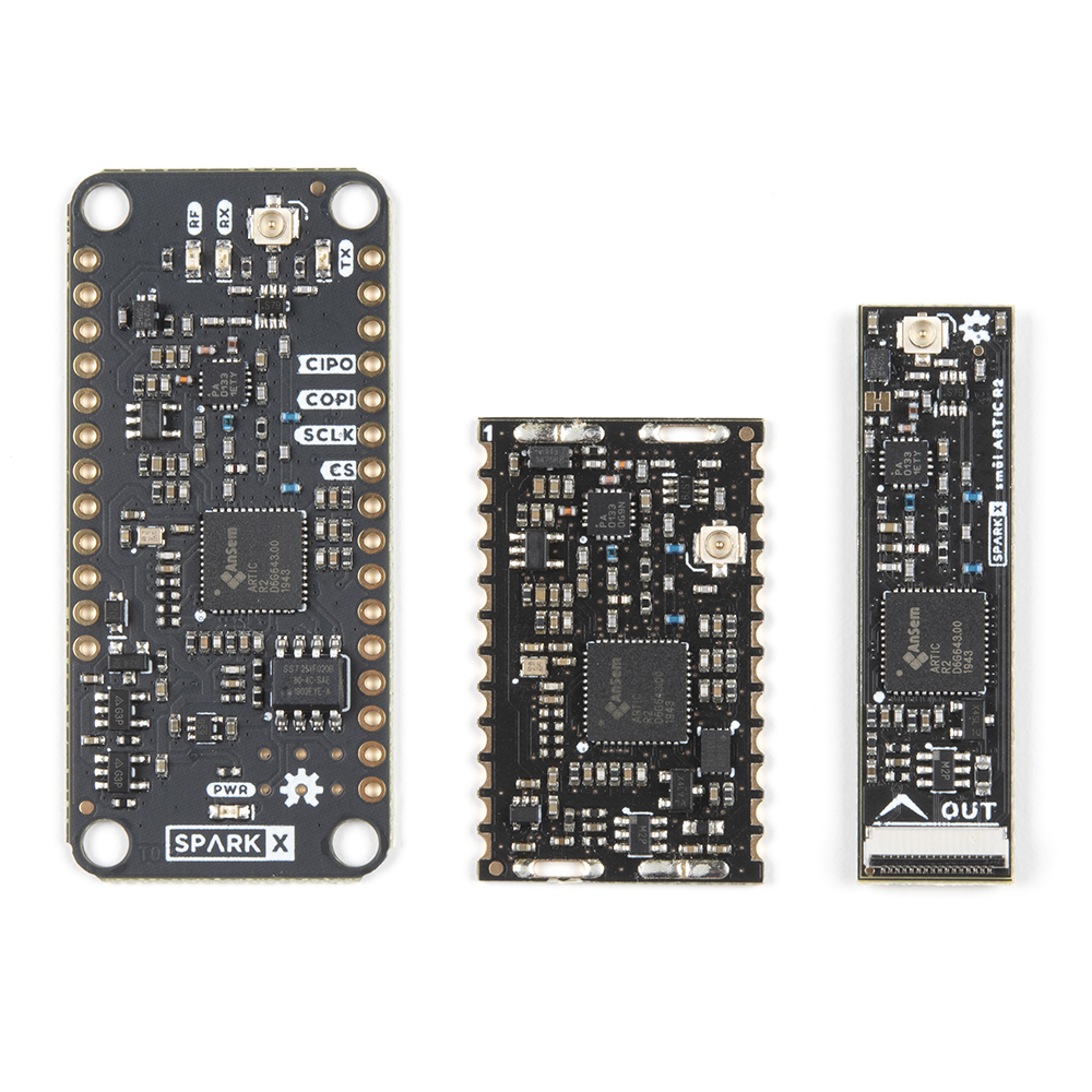
We offer three ARGOS ARTIC R2 satellite transceiver products:

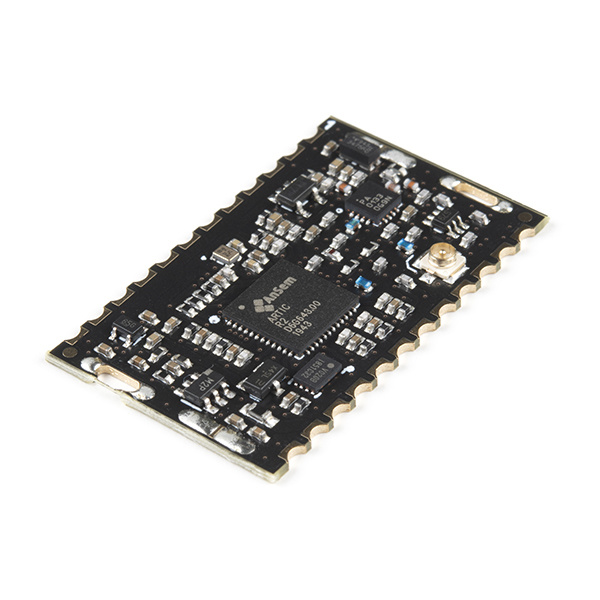
This board, the IOTA - the Integrated Open source Transceiver for ARGOS - is ideal if you are ready to incorporate an ARGOS transceiver into your design. Its castellated pads can be reflowed or hand-soldered as required. It also has slots for an RF screening can, should your certification process require one. The antenna connection is available on both a castellated pad and a u.FL connector. You will find an Eagle symbol and footprint for IOTA in the SparkFun Eagle Libraries RF Library.
The ARGOS Satellite Transceiver Shield - ARTIC R2, is the biggest of the three and the easiest to get your fingers around. It has the same footprint as our Feather-compatible Thing Plus boards and is designed to stack directly on top of a Thing Plus for easy development. If you are looking for a board to allow you to get to know how ARGOS satellite communication works, or are just starting out on your product development, or want a board you can plug into breadboard, or are not worried about making your tracking system as compact as possible, then this is the board for you.
The smôl ARTIC R2 is the baby of the three, but it still packs the same punch as its larger siblings. If you are developing a compact dart for whale tracking, or a small backpack for avian tracking, or a very discrete satellite tracker, then the smôl ARTIC R2 is the one for you.

All three boards use the same ARTIC R2 satellite transceiver chip. All three have the same power amplifier, with the same maximum output power and adjustable gain. All three have the same receive sensitivity. All three have on-board flash memory containing the ARTIC R2 firmware and Platform ID. All three are supported by our comprehensive Arduino Library which includes a full set of tried-and-tested examples.
If you would like to know more about the ARGOS satellite network itself, head on over to our ARGOS (ARTIC R2) Satellite Communication Guide:
ARGOS & ARTIC R2
The ARGOS satellite system has been around for quite a while. It was created in 1978 by the French Space Agency (CNES), the National Aeronautics and Space Administration (NASA) and the National Oceanic and Atmospheric Administration (NOAA), originally as a scientific tool for collecting and relaying meteorological and oceanographic data around the world. Today, ARGOS is revolutionising satellite communication, adding a constellation of 25 nanosatellites to complement the 7 traditional satellites carrying ARGOS instrumentation. The first of these, ANGELS, is already in operation and SparkFun were among the first users to transmit data to ANGELS in October 2020. When the constellation is complete, there will be a maximum of 10-15 minutes between satellite passes.
The ARTIC R2 is an integrated, low-power, small-size ARGOS 2/3/4 single chip transceiver. ARTIC implements a message based wireless interface. For satellite uplink communication, ARTIC will encode, modulate and transmit provided user messages. For downlink communication, ARTIC will lock to the downstream, demodulate and decode and extract the satellite messages. The ARTIC can transmit signals in frequency bands around 400MHz and receive signals in the bands around 466MHz, in accordance with the ARGOS satellite system specifications.
The IOTA has been tested and certified by Kinéis. Compared to other satellite communication systems, the ARTIC R2 has a much lower current draw and will work with a very simple, very lightweight quarter-wave wire antenna. The ARTIC R2 chipset on IOTA operates from 3.3V and the on-board flash memory enables fast boot times. If you don’t need the full transmit power, or want to conserve your battery life, you can transmit at reduced power too thanks to opto-isolated gain control.
Our Arduino Library makes it really easy to get up and running with ARGOS. We’ve provided a full set of examples which will let you: configure the ARTIC R2 chipset; predict the next satellite pass; receive allcast and individually-coded messages; transmit messages using ARGOS 2, 3 and 4 encoding.
Hardware Overview
In this section we'll cover what's included on the IOTA (ARTIC R2) Satellite Communication Module.
ARTIC R2
The heart of IOTA is, of course, the ARTIC R2 transceiver itself. This is a clever chip containing a Digital Signal Processor (DSP) which modulates transmit messages and demodulates received messages. The DSP can boot from on-board flash memory or from an external microcontroller via SPI. When transmitting, it produces a 1mW (0dBm) output signal which is fed to a separate power amplifier.
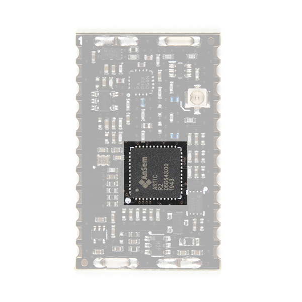
Our Arduino Library does all of the heavy lifting for you. By default, the library will tell the ARTIC R2 DSP to boot from the on-board flash memory. However, by changing one line of code, you can instead boot via SPI with your microcontroller providing the firmware for the DSP.
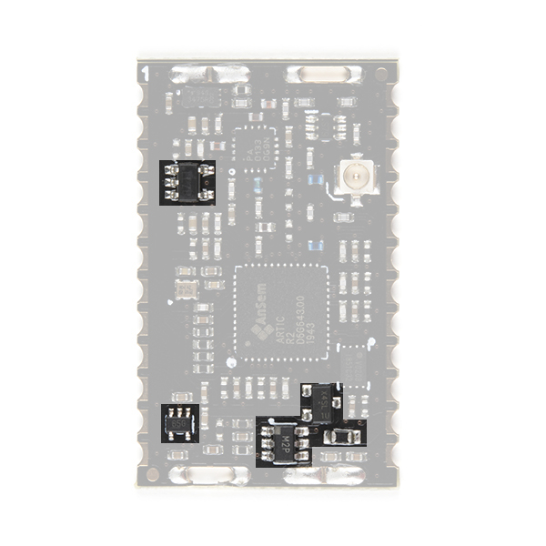
RF Amplifier
During transmit, the RFPA0133 power amplifier boosts the 0dBm (1mW) signal from the ARTIC R2.
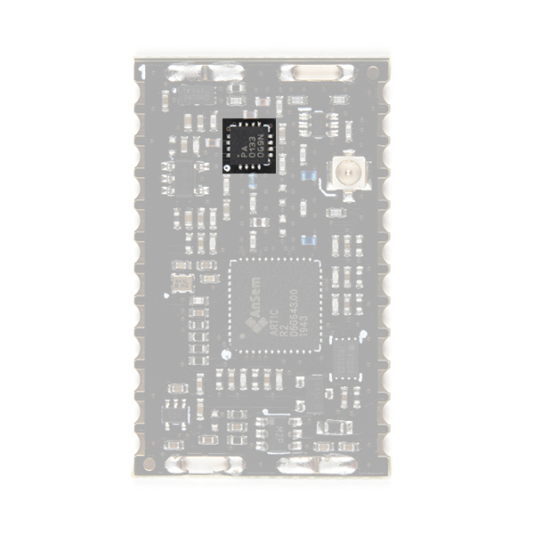
Using full gain, the amplifier boosts the signal to approximately 25.7dBm (370mW). If you are using ARGOS 2 or 3 modulation and are transmitting from a 'noisy' environment, like a city, then you are probably going to need to use full power to ensure your messages get through. However, if you are using ARGOS 4 modulation and/or are transmitting from a 'quiet' environment, like the tundra or the ocean, then you will be able to transmit at reduced power.
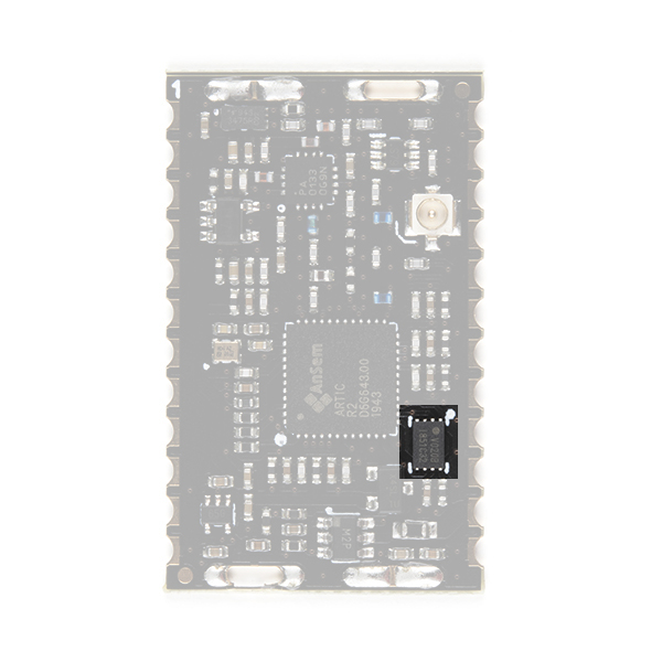
Gain Control
You can adjust the transmit gain through software and the on-board opto-isolated gain control circuit.
Our Arduino Library can reduce the gain for you. If you call:
language:c
myARTIC.attenuateTXgain(true);
from inside your code, the opto-isolator will pull the RFPA0133's G8 pin low, reducing the gain by approximately 5dB. This also has the advantage of reducing the transmit current by approximately 80mA.
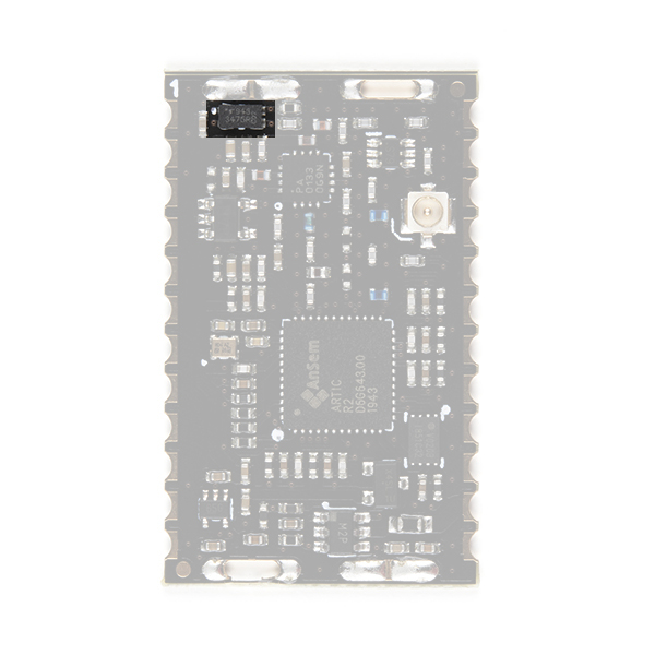
Flash Memory
By default, the DSP inside the ARTIC R2 will boot from the on-board flash memory. (But, as mentioned above, you also have the option of booting via SPI.)
During production testing at SparkFun, we program the flash memory with the ARTIC R2 firmware (ARTIC006) and a Platform ID allocated by CLS. You will need to register the Platform ID on your ARGOS account to activate it. The Arduino Library reads the Platform ID from memory and uses it in the transmissions.
Antenna
On IOTA, you have a choice of antenna connection: u.FL; or a castellated pad.
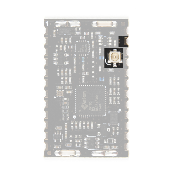
Check out our tutorial if you haven't used u.FL before:
Three Quick Tips About Using U.FL
Power Circuit
The IOTA requires a 3.3V ±0.1V DC power supply able to cope with the maximum transmit current of 230mA.
The power circuit comprises: in-rush and over-current protection; 3.0V and 1.8V regulators.
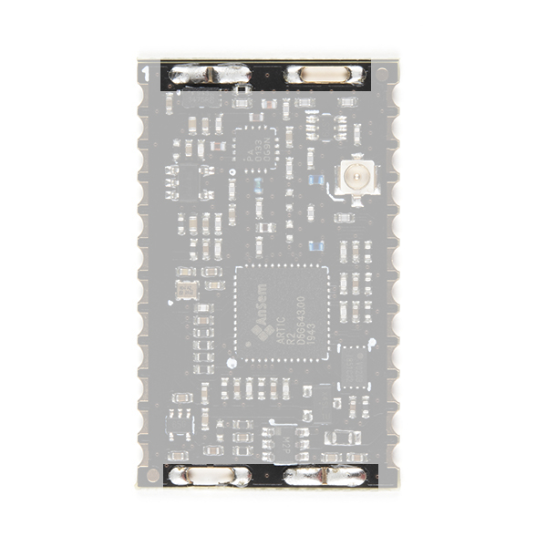
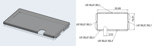
Screening Can
IOTA has slots and ground pads for an RF screening can, should your certification process require one.
You can find the design for the screening can on onshape. You can right-click on the onshape document tabs and select Export... to export the design in a variety of formats.
Castellated Pads
The IOTA has 24 castellated pads. It can be reflowed or hand-soldered onto a PCB depending on your needs.
You will find an Eagle symbol and footprint for IOTA in the SparkFun Eagle Libraries RF Library.
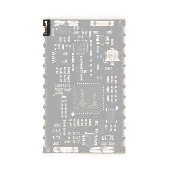
The photo below shows the bottom of IOTA. Pad 1 is top right.
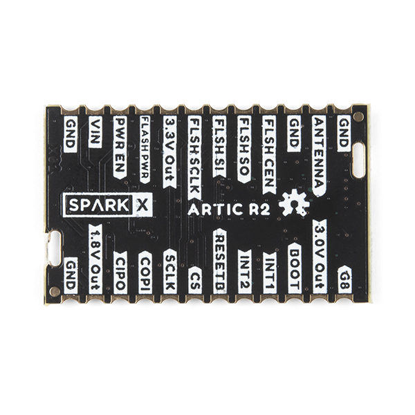
The table below describes the function of each of the IOTA's castellated pads. Looking at IOTA from the top, pad 1 is top left. Pad numbering is counter-clockwise.
| Pad No. | Name | Function | Description | |
|---|---|---|---|---|
| 1 | G8 | INPUT | Pull up to 3.3V to set the RFPA0133 transmit power to maximum. The transmit power will be reduced by _approximately_ 5dB if this pin is pulled low or left open. | |
| 2 | 3.0V Out | OUTPUT | This pad allows measurement of the module's internal 3.0V rail. | |
| 3 | BOOT | INPUT | Connected to the ARTIC BOOT pin. Pulled up to 3.3V via a 100k resistor. When high, the ARTIC boots from the external flash memory. Pull low if the ARTIC firmware will be downloaded by the MCU via SPI. | |
| 4 | INT1 | OUTPUT | Connected to the ARTIC INT1 pin. Will be pulled up to 3.3V by the ARTIC to indicate (e.g.) an RX_VALID_MESSAGE. | |
| 5 | INT2 | OUTPUT | Connected to the ARTIC INT2 pin. Will be pulled up to 3.3V by the ARTIC to indicate (e.g.) an RX_BUFFER_OVERFLOW. | |
| 6 | RESETB | INPUT | Connected to the ARTIC reset pin. Pulled up to 3.3V via a 100k resistor. Pull low to reset the ARTIC. | |
| 7 | CS | INPUT | SPI interface Chip Select. 3.3V. Active low. | |
| 8 | SCLK | INPUT | SPI interface clock signal. Typically 1MHz. 3.3V. See the ARTIC R2 datasheet for the permitted clock speeds. | |
| 9 | COPI | INPUT | SPI interface: Controller Out Peripheral In. 3.3V. | |
| 10 | CIPO | OUTPUT | SPI interface: Controller In Peripheral Out. 3.3V. | |
| 11 | 1.8V Out | OUTPUT | This pad allows measurement of the module's internal 1.8V rail. | |
| 12 | GND | Power ground / 0V. | ||
| 13 | GND | Power ground / 0V. | ||
| 14 | VIN | INPUT | 3.3V power supply for the module. Voltage must be: 3.3V +/- 0.1V. Current limit: 500mA. | |
| 15 | PWR EN | INPUT | Pulled low via a 10k resistor. Pull up to 3.3V to enable power for the ARTIC R2. | |
| 16 | FLASH_PWR | INPUT | 3.3V power supply for the internal flash memory. Connect to Pin 17 (3.3V Out). | |
| 17 | 3.3V Out | OUTPUT | Connected to the module's internal 3.3V rail (switched) and provides power for the internal flash memory. Connect to Pin 16 (FLASH PWR). | |
| 18 | FLSH SCLK | Clock signal for the internal SST25VF020B 2-Mbit SPI Serial Flash. Used when programming the internal flash memory. Leave unconnected. | ||
| 19 | FLSH SI | Serial Data In for internal SST25VF020B 2-Mbit SPI Serial Flash. Used when programming the internal flash memory. Leave unconnected. | ||
| 20 | FLSH SO | Serial Data Out for internal SST25VF020B 2-Mbit SPI Serial Flash. Used when programming the internal flash memory. Leave unconnected. | ||
| 21 | FLSH CEN | Chip Enable for internal SST25VF020B 2-Mbit SPI Serial Flash. Used when programming the internal flash memory. Leave unconnected. | ||
| 22 | GND | Power ground / 0V. | ||
| 23 | ANTENNA | RF | Antenna connection (50 Ohm). Connected internally to the center pin of the u.FL connector. | |
| 24 | GND | Power ground / 0V. |
Arduino Example: Satellite Detection
The SparkFun ARGOS ARTIC R2 Arduino Library contains a full set of tried and tested examples which will run on any Arduino board, but you will need to change the pin definitions in the code to match your board.
This guide assumes you already have the Arduino IDE and the ARGOS ARTIC R2 Library installed, and have selected the correct Arduino Board. If you need help with any of that, please check out the ARGOS ARTIC R2 Shield Hookup Guide.
The code below is a stripped-down version of Example4_SatelliteDetection. Copy and paste the code into a new window in the Arduino IDE:
language:c
#include <SPI.h>
#include "SparkFun_ARGOS_ARTIC_R2_Arduino_Library.h" // http://librarymanager/All#SparkFun_ARGOS_ARTIC_R2
ARTIC_R2 myARTIC;

// Pin assignments - change these if required
int CS_Pin = 24;
int GAIN8_Pin = 3;
int BOOT_Pin = 4;
int INT1_Pin = 5;
int INT2_Pin = 6;
int RESET_Pin = 7;
int IOTA_PWR_EN_Pin = 8;

void setup()
{
  Serial.begin(115200);
  Serial.println(F("ARGOS ARTIC R2 Example"));

  Serial.println(F("ARTIC R2 is booting..."));

  SPI.begin();

  //myARTIC.enableDebugging(); // Uncomment this line to enable debug messages on Serial

  // Begin the ARTIC: enable power and boot from flash
  if (myARTIC.beginIOTA(CS_Pin, RESET_Pin, BOOT_Pin, IOTA_PWR_EN_Pin, INT1_Pin, INT2_Pin, GAIN8_Pin) == false)
  {
    Serial.println("ARTIC R2 not detected. Freezing...");
    while (1)
      ; // Do nothing more
  }

  Serial.println(F("ARTIC R2 boot was successful."));

  // Read the Platform ID from flash memory
  uint32_t platformID = myARTIC.readPlatformID();
  if (platformID == 0)
  {
    Serial.println(F("You appear to have an early version of the SparkFun board."));
    Serial.println(F("For the transmit examples, you will need to use the Library Manager to select version 1.0.9 of this library."));
  }
  else
  {
    Serial.print(F("Your Platform ID is: 0x"));
    Serial.println(platformID, HEX);
  }

  myARTIC.setTCXOControl(1.8, true); // Set the TCXO voltage to 1.8V and autoDisable to 1

  myARTIC.setSatelliteDetectionTimeout(600); // Set the satellite detection timeout to 600 seconds

  Serial.println(F("Starting satellite detection..."));

  // Start satellite detection
  // The ARTIC will start looking for a satellite for the specified amount of time.
  myARTIC.sendMCUinstruction(INST_SATELLITE_DETECTION);
}

void loop()
{
  delay(1000);

  // Read the ARTIC R2 status register
  ARTIC_R2_Firmware_Status status;
  myARTIC.readStatusRegister(&status);

  // Check the interrupt 2 flag. This will go high if satellite detection times out
  if (status.STATUS_REGISTER_BITS.DSP2MCU_INT2)
  {
    Serial.println(F("INT2 pin is high. Satellite detection has timed out!"));
  }
  // Check the interrupt 1 flag. This will go high when a satellite is detected
  else if (status.STATUS_REGISTER_BITS.DSP2MCU_INT1)
  {
    Serial.println(F("INT1 pin is high. Satellite detected!"));
  }

  // Check the instruction progress
  // checkMCUinstructionProgress will return true if the instruction is complete
  ARTIC_R2_MCU_Instruction_Progress progress;
  boolean instructionComplete = myARTIC.checkMCUinstructionProgress(&progress);

  if (instructionComplete)
  {
    Serial.println(F("Satellite detection is complete! Freezing..."));
    while (1)
      ; // Do nothing more
  }
}
Save the file and click on the Upload button to upload the example onto your Arduino board. Open Tools\Serial Monitor to see the serial messages. Check that the baud rate is set to 115200:
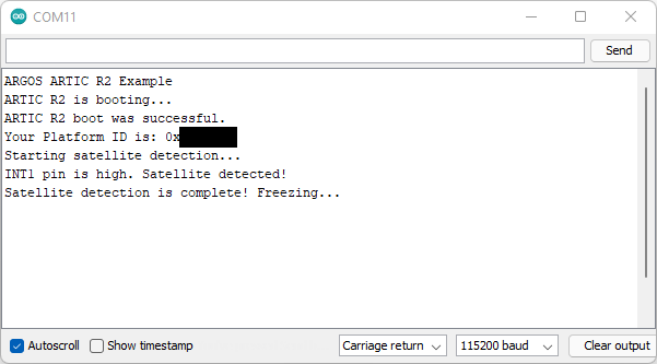
Once the ARTIC R2 has booted, the code will read the pre-programmed Platform ID from flash memory. If it does not find one, you will see a message reminding you to install v1.0.9 of the ARTIC R2 library.
The ARTIC R2 will try to detect a satellite for up to 10 minutes. You may wish to log into the ARGOS website and predict when the next satellite pass will take place before running this example.
Current Draw
Knowing the current drawn by the IOTA is of course very important when calculating your battery life.
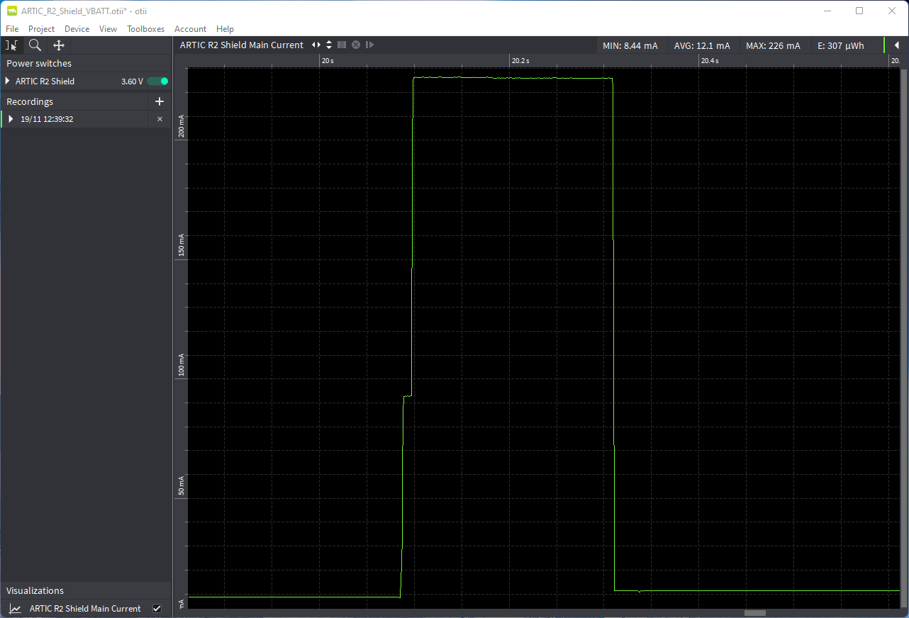
We measured the ARTIC R2 Shield's current draw using the fantastic Otii Arc Power Analyzer. IOTA is functionally identical to the Shield and the current draw is the same. The Otii Arc was configured to output 3.6V and we connected it to the Shield's VBATT pin to replicate a LiPo battery.
- Current Draw:
- Sleep (PWR EN and RF EN low): 51µA
- Idle (power LEDs enabled): 7.2mA (AVG)
- Receive: 32.9mA
- Transmit (full power, G8 pin high): 226mA
- Transmit (reduced gain, G8 pin low): 170mA
Here is the data captured by Otii Arc when transmitting ARGOS 3 ZE data at full power:
And here is the current draw when transmitting ARGOS 3 ZE data at reduced power:

Certification
IOTA has been tested and certified by Kinéis, who are responsible for the operation of the ARGOS system. You can find copies of the test certificates below.
- ARGOS 4 VLD Certificate (IOTA)
- ARGOS 2 Certificate (ARGOS ARTIC R2 Satellite Transceiver Shield)
- ARGOS 3 Certificate (ARGOS ARTIC R2 Satellite Transceiver Shield)
We are very grateful for the time and effort Kinéis have spent testing the SparkFun ARTIC R2 products.
Troubleshooting
Resources and Going Further
For more information about IOTA, check out the following links:
IOTA Documentation:
- Schematic
- Eagle Files
- SparkFun Eagle RF Library
- ARGOS Chipset Info Sheet
- ARTIC R2 User Datasheet v1.1
- GitHub Hardware Repo
- Arduino Examples
- SparkFun ARGOS ARTIC R2 Arduino Library
ARGOS ARTIC R2 Documentation: