IOIO-OTG Hookup Guide
 Joel_E_B, Ytai
IOIO Board Overview
This section will cover the various parts and features found on the IOIO-OTG board.
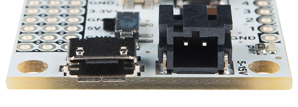
USB Micro-AB Connector
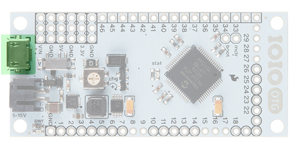
The micro USB connector is used to connect the IOIO to a number of devices. You can connect the IOIO to a PC using a micro-B USB Cable. The supplied USB Female A to micro-A OTG Cable should be used whenever connecting to an Android device, with the IOIO acting as host (for charging the Android), OR to a Bluetooth dongle.
Power
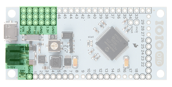
Power LED
In the bottom-left corner of the image, we have the red power LED. This illuminates when the IOIO is powered through either the USB port, the JST connector or the VIN pins.
2-pin JST Female Power Jack
Used for power supply to the board. Voltage between 5V--15V should be supplied. The simplest way to power the IOIO-OTG is to use a wall power supply (5--15V) coupled with our Barrel Jack to JST adapter. Consider a supply that is 1.5V+ higher than 5V. This will result in a more stable 5V supply coming from the voltage regulator.
VIN pins (3 pins)
Used for outputting the supply voltage to your circuit, or as an alternative input to the power jack.
5V Pins (3 pins)
5V output from the onboard regulator, which can be used in your circuit.
3.3V Pins (3 pins)
3.3V output from the onboard regulator, which can be used in your circuit.
You can read more about ways to power the IOIO-OTG here.
GPIO Pins
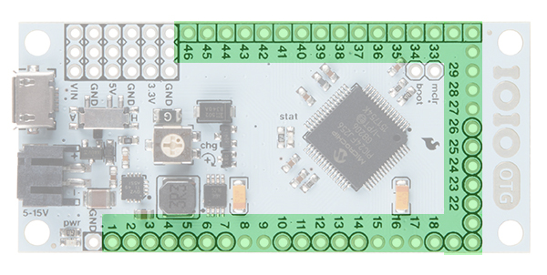
General Purpose Input/Output (GPIO) pins are the meat of the IOIO-OTG and are the pins used to interface your applications to the physical world. All 46 pins can be used as 3.3V digital input (pull-up / pull-down / floating) or output (push-pull / open-drain). Several pins have additional functionality. Luckily, there is a handy key located on the back of the IOIO to clarify which pins are capable of which functions.
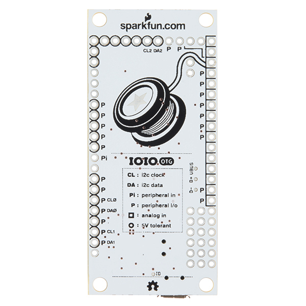
To clarify, the key is as follows:
- Pins with Black Circles around them can be used as 5V Tolerant I/O. Pins without circles should only be used with 3.3V devices.
- Pins with Black Squares can be used as Analog Inputs.
- Pins marked with a 'P' can be used as Peripheral Inputs/Outputs.
- Pins marked with a 'Pi' can be used as Peripheral Inputs only.
- Pins marked with CL or DA can be used as the Clock and Data lines for the various I2C ports on the IOIO. There are three I2C ports available on the IOIO-OTG.
By default, pins might be damaged if exposed to voltage outside the 0V-3.3V range. 5V-tolerant pins extend this range to 0V-5V, thus allowing us to communicate with 5V logic.
You can read more about the IOIO-OTG's I/O pins here.
Status LED
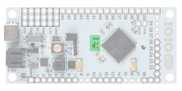
Normally, this yellow LED is under application control (“pin 0”). In very few special cases (e.g., bootloader mode), it has a special meaning (to indicate entry into bootloader mode or an unconfigured oscillator).
Charge Current Trimpot (CHG)
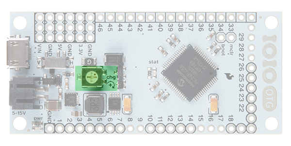
The CHG adjusts the amount of current supplied on the VBUS line of the USB when acting as a USB host (or when it is connected to your Android). It is typically used in battery-powered applications to prevent battery drain. Turning in the clockwise (+) direction increases charge current. Generally, this can be left at the default factory setting, which is fully clockwise.
Host/Device Switch
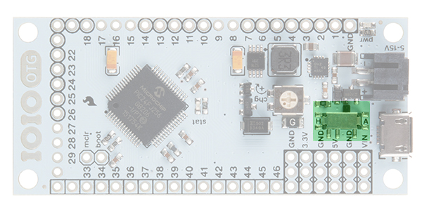
Not normally used. Keep switch in A mode. In “A” mode, the IOIO-OTG will detect whether it should act as host or as device automatically, according to whichever USB connector is plugged in (micro-A or micro-B). The only reason to put it in H mode is when working with a non-standard USB-OTG cable or adapter that doesn’t identify itself correctly on the host side or the cable. This should never be the case with the provided USB-OTG cable.
MCLR and Boot Pins
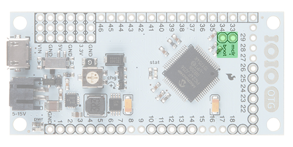
MCLR
This pin hardly ever needs to be used by the user. This pin is for programming a new bootloader onto the IOIO-OTG board.
BOOT
This pin will only be used on occasion by the user for firmware upgrades. This pin is used to switch the IOIO-OTG into bootloader mode on power-up. Note that this pin is shared with the Stat LED.
More information about the IOIO-OTG hardware can be found here.