Installing libmraa on Ubilinux for Edison
 caseyd
The Circuit
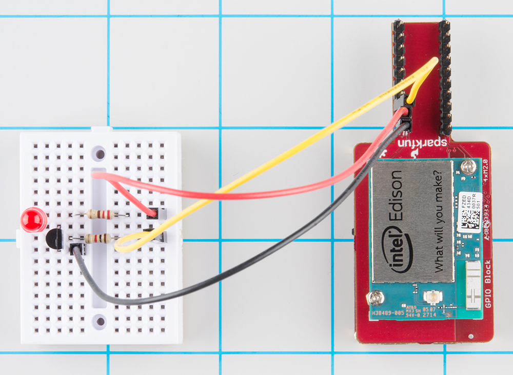
The first thing to do is connect up the LED. For this tutorial, we used an Intel Edison, a Base Block, and a GPIO Block. You can also use the Console Block, Mini Breakout Board, or Arduino Breakout Board.
Parts List
In addition to the Edison and breakout board(s), you will need some basic components. Below is the list of components used in this tutorial. Note that from the resistor kit, we used a 1 kΩ and 220 Ω resistor.
Schematic
Unless you are using the Edison Arduino Breakout board, the Edison cannot supply enough current to fully (and safely) light an LED. As a result, we need to make a basic switch using a BJT transistor.
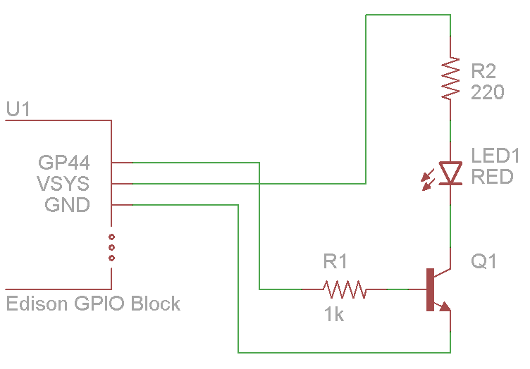
Note: If you are using the Arduino Breakout Board, you do not need to use this circuit, as the Arduino board can provide enough current. You will want to use the pin labeled A0, as noted in Table 3 of the Arduino Breakout Hardware Guide.
Also Note: if you are using the Mini Breakout Board, you will want to use GP44 (J19, pin 4) according to the Breakout Board Hardware Guide.
Connections
Connect your LED circuit to the GPIO Block as shown.
- 220 Ω Resistor (Pin 2) → LED (Anode)
- 2N3904 (Collector) → LED (Cathode)
- 2N3904 (Base) → 1 kΩ Resistor (Pin 2)
- GPIO Block (GND) → 2N3904 (Emitter)
- GPIO Block (VSYS) → 220 Ω Resistor (Pin 1)
- GPIO Block (GP44) → 1 kΩ Resistor (Pin 1)
Important: Note the direction of the LED and transistor! In the photo, the flat edge of the LED is pointing down (towards the transistor), and the flat edge of the transistor is pointing to the right (towards the resistors).