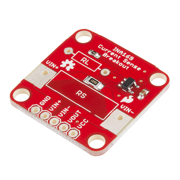
INA169 Breakout Board Hookup Guide
Introduction
Have a project where you want to measure the current draw? Need to carefully monitor low current through an LED? The INA169 is the chip for you!
The INA169 is a "high-side current monitor," which means that you place a resistor (a "shunt resistor") on the positive power rail and the INA169 measures the voltage drop across that resistor. The INA169 outputs a small current based on the measured voltage drop. If you place a resistor from the output of the INA169 to ground, you can measure the voltage at the output. With some basic math, the output voltage gives you the current through the shunt resistor.
Covered In This Tutorial
In this tutorial, we cover how the board should be used. The Board Overview section covers some theory and math on how the current sensing works, so feel free to skip to the Hookup Example if you just want to see the board in action. The Hookup Example shows how to connect the board to an Arduino in order to measure the current through an LED, and the Example Code provides a quick Arduino sketch for displaying the measured current to the Serial Monitor.
Required Materials
- Arduino, RedBoard or any Arduino-compatible board.
- Male headers to solder to the board and make it breadboard compatible.
- Jumper wires to connect from breadboard to Arduino.
- Breadboard to tie everything together.
- Basic Red LED so we have something to light up.
- 330Ω Resistor to limit the current through the LED.
Suggested Reading
- Voltage, Current, Resistance, and Ohm's Law
- Resistors
- LEDs
- How to Use a Breadboard
- What is an Arduino?
- How to Solder
- Working with Wire
