INA169 Breakout Board Hookup Guide
 Shawn Hymel
Hookup Example
Assembly
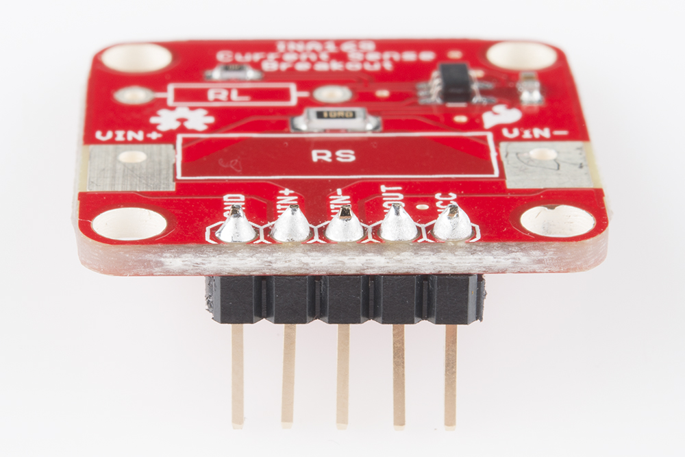
You will need to solder either wires or straight male headers to the 5 header holes on the board. If you need to measure over 35mA, you will need to desolder the RS resistor and solder a lower value (e.g. 1Ω), higher power (e.g. 3W) resistor to the holes around RS.
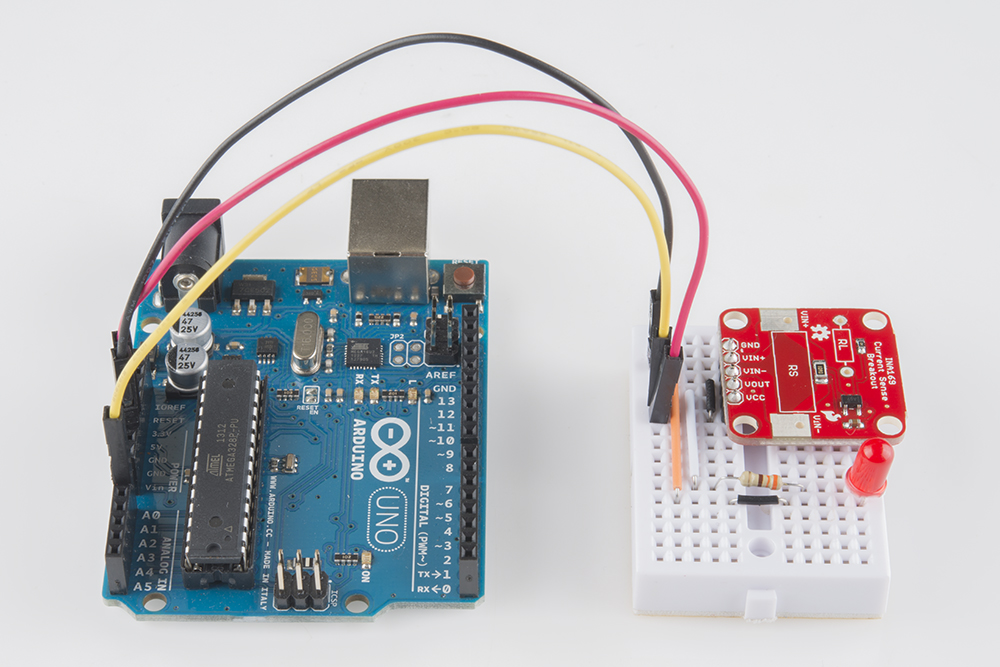
Connecting the INA169 Breakout Board
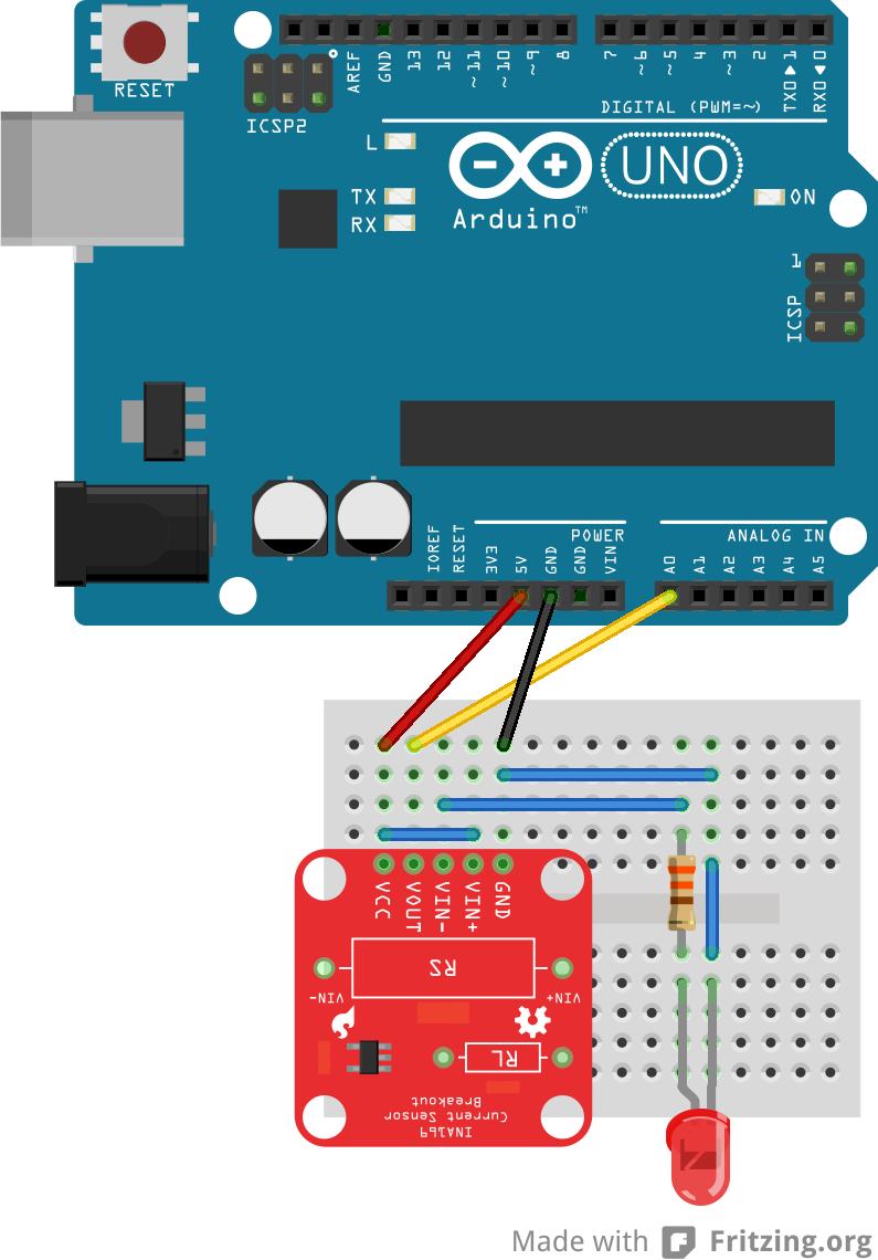
As shown in the diagram, connect the Arduino 5V to the INA169 VCC and the Arduino GND to the INA169 GND. To read the output voltage level, we need to run a jumper cable from the Arduino A0 to the INA169 VOUT pin.
Use a jumper wire to connect the INA169 VCC and VIN+ pins, as we want to power the LED with the Arduino 5V. If you use a different power source (other than the Arduino 5V or 3.3V) through VIN+ and VIN-, make sure you connect the ground of the power source to the ground of the INA169 board. Just ensure that the voltage level as measured from VIN+ to ground does not exceed 60V. Bad things will happen to the board if you do.
Connect a 330Ω resistor from the INA169 VIN- to the anode of the LED and a jumper wire from the LED's cathode to GND.
If you want to measure the current going to something else, you can use alligator clips on the bare metal pads around RS. Make sure that the INA169 board is inline with the positive power rail and that the INA169 GND is connected to the target's GND.