INA169 Breakout Board Hookup Guide
 Shawn Hymel
Board Overview
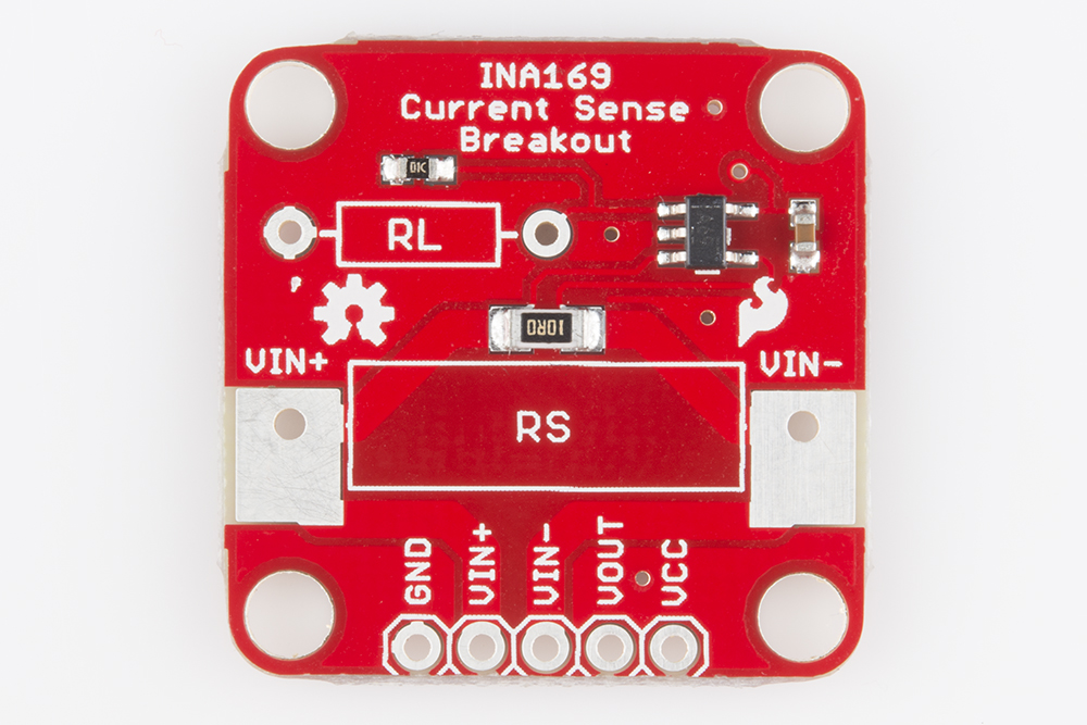
Take a look at the schematic, and you will notice that the breakout board consists of a shunt resistor (RS), the INA169 chip, and an output resistor (RL). While RS and RL might appear to have 2 resistors, only one is populated on the board. If you would like to change the values of the resistors, you can replace them or put another resistor in parallel.
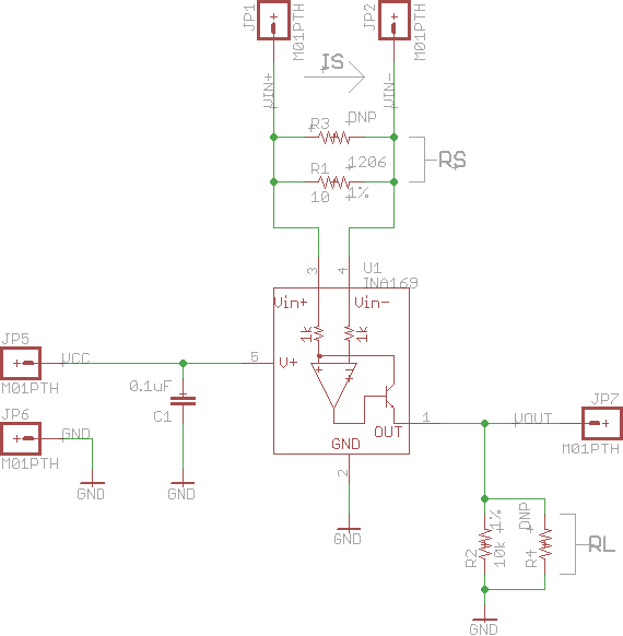
As current passes from VIN+ through RS to VIN-, it creates a voltage drop across RS. The op-amp inside of the INA169 chip measures the difference between the VIN+ and VIN- voltages and outputs a voltage based on that difference. The output of the op-amp is amplified through the internal transistor, which sources a current out of the INA169 chip. As that current passes through RL to ground, a voltage level is generated at VOUT.
Measuring Current
The voltage at VOUT can be measured using an oscilloscope or an analog-to-digital converter. A bit of math is needed to convert to the source current (IS):
IS is the current we want to measure.
VOUT is the voltage we measured at the output of the INA169.
1kΩ is a constant resistance value we need to include due to the internals of the INA169.
RS is the value of the shunt resistor. If you do not modify the board, then this is set at 10Ω.
RL is the value of the output resistor. If you do not modify the board, then this is set at 10kΩ.
Example
For example, let's say that you hook up the board and you measure 2.8V at VOUT. Plugging this into our equation, we would get:
This shows that you have 0.028A (or 28mA) flowing through your line.
The Pinout
There are only 5 pins on the breakout board.
GND should be connected to ground of the circuit you are trying to measure
VIN+ needs to be connected to the positive side of the source (e.g. battery, output pin, etc.)
VIN- needs to be connected to the positive side of the load (e.g. VCC on Arduino, positive side of an LED, etc.)
VOUT is the measured output and should be connected to something that measures voltage levels, such as a multimeter, oscilloscope, or an Arduino ADC pin
VCC is the supply power to the INA169, which needs to be connected to 3.3V, 5V, etc. This can be anywhere from 0 to 75V. Note that the VOUT range depends on the voltage supplied by VCC.
In addition to the pins on VIN+ and VIN-, the board also has two large pads around RS, which are capable of taking alligator clips should you want to have a temporary hookup. Note that GND and VCC will still need to be connected for the board to function.
Modifying Functionality
The INA169 cannot sense any differences across RS greater than 500mV, and the output error increases once the voltage across RS dips below 35mV. If you include the voltage drop across the internal transistor, this means that the default setup of the breakout board is limited to measuring a current range of about 3.5mA to 35mA.
If you would like to change that range, RS and RL can be replaced with resistors of different values. RS can be removed and replaced with another resistor fairly easily. RL is a bit more difficult as it is a small, surface mount resistor. Changing either of the resistors changes the equation from above.
With RL at 10kΩ, changing RS gives us the following ranges:
| RS | Current Sense Range |
| 10Ω | 3.5mA - 35mA |
| 1Ω | 35mA - 350mA |
| 0.1Ω | 350mA - 3.5A |
- Ohmite 1Ω 1% 3W
- Ohmite 0.1Ω 1% 3W
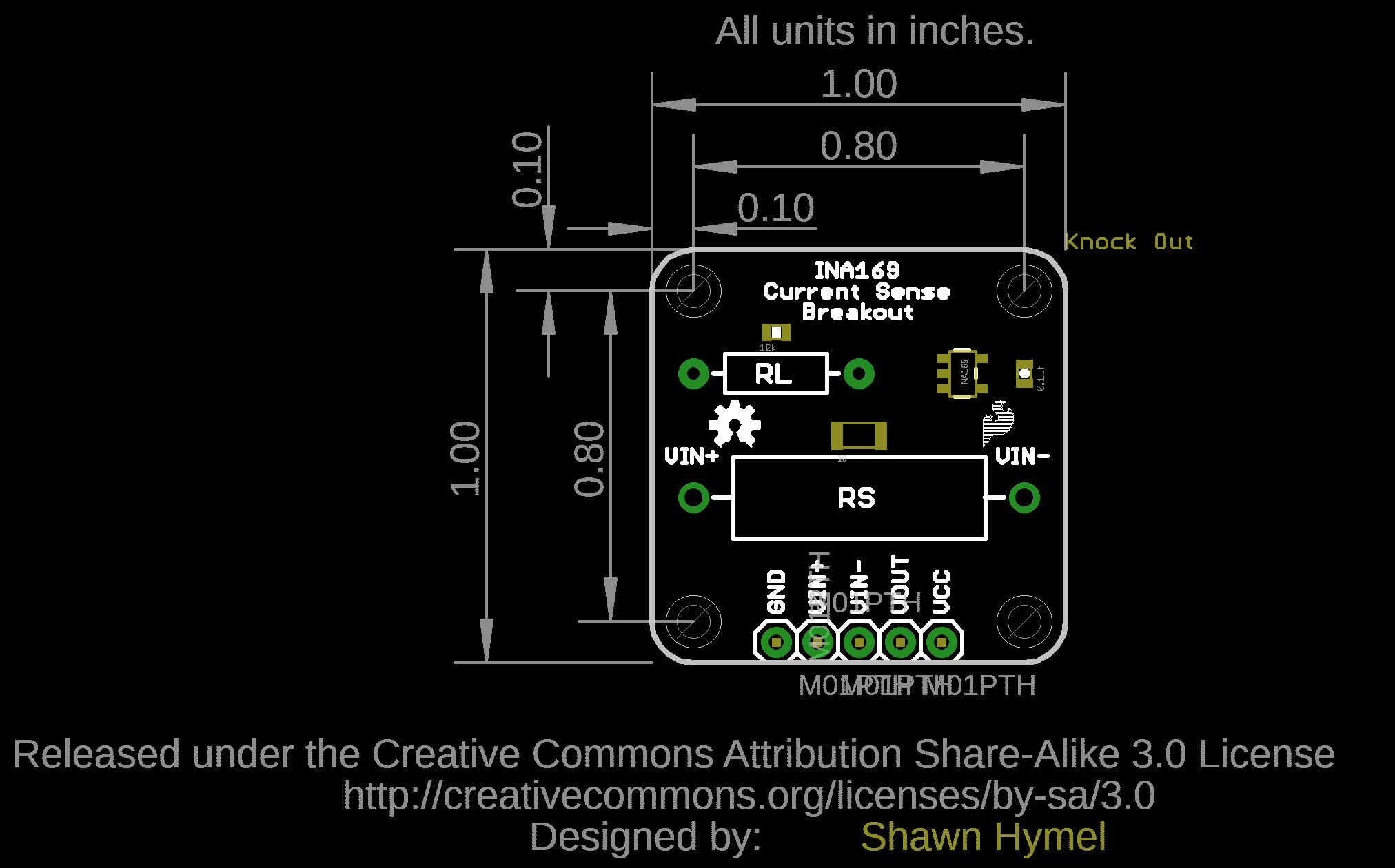
Board Dimensions
The board dimensions is 1.0" x 1.0" and includes 4x mounting holes by each corner of the board.