HX1 APRS Transmitter Hookup Guide
 MikeGrusin
Hardware Overview
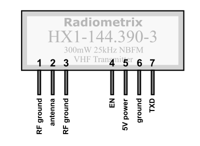
The HX1 has seven pins in two groups:
| Pin | Function | Notes |
|---|---|---|
| 1 | RF Ground | Antenna ground or coax shield |
| 2 | Antenna Output | Antenna or coax center |
| 3 | RF Ground | Antenna ground or coax shield |
| 4 | EN (Enable) Input | 5V to transmit, 0V for standby |
| 5 | 5V Power Input (VCC) | Regulated 5V power supply at 140mA |
| 6 | Ground | Ground of regulated power supply |
| 7 | TXD (Transmit Data) Input | 5V signal with modulation and formatting |
Power Supply
The HX1 requires a regulated 5V supply capable of providing 140mA when it's transmitting (it uses essentially no current in standby). The voltage regulator already present on a 5V Arduino should be able to handle this.
EN (Enable) Input
The EN or enable pin controls whether the module is transmitting or in standby mode (sometimes this is called a PTT or "Push To Talk" control). Since APRS uses a shared frequency, it's important to only transmit during the brief time that a packet is being sent and stay silent otherwise; this lets many people share the frequency. To transmit, the EN pin must be set to a high logic level (5V).
After enabling the transmitter, it's a good idea to wait 5ms before sending any data to the TXD pin. Your software should handle this automatically.
TXD (Transmit Data) Input
It's important to note that the HX1 is a bare transmitter and doesn't do any modulation or packetizing on its own. The TXD data input must be modulated properly in order to transmit properly. Modulation and packetizing is a broad topic beyond the scope of this tutorial, but there are several Arduino projects designed to connect to the TXD pin of the HX1 and send data. We'll cover one of these projects below.
Antenna
The HX1 requires an antenna to transmit. You can buy one (search for "2 meter antenna" as the APRS frequency is in the 2-meter amateur radio band), or you can build one.
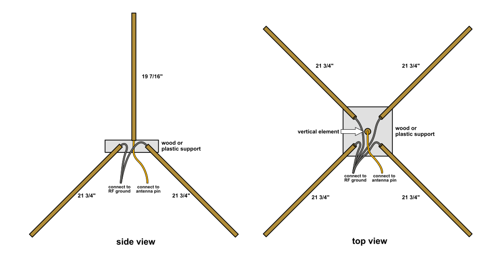
There are many antenna designs out there, but a simple quarter-wave ground plane antenna works well and is easy to make. This antenna features a vertical element surrounded by four radial elements angled down at 45 degrees:
The length of an antenna's elements depends on the frequency. For the 144.390MHz frequency we'll be using, the element lengths are:
| Antenna | Length | |
|---|---|---|
| Vertical Element (1x): | 19 + 7/16" | 493mm |
| Radial Elements (4x): | 21 + 3/4" | 553mm |
The elements can be made of any conductive metal, but brass and copper rods are easy to solder to. The rods can be supported in position by any nonconductive material (plastic, wood, etc.).
To connect the antenna to the HX1, connect the vertical element to the antenna output pin (2), and the radial elements to the RF ground pins (1,3) on either side of the antenna pin.
If the HX1 transmitter will be more than a couple inches away from the antenna, use 50-ohm coaxial cable to connect the RF pins to the antenna. Connect the antenna output pin (2) to the center conductor of the coax, and the outer RF ground pins (1,3) to the shield. On the antenna side, connect the center conductor to the vertical element, and the shield to the radial elements or ground plane.
For maximum range, locate your antenna as high as practical and away from nearby metal objects PVC pipe is a good nonconductive structural material for this.
Note that this antenna design is omnidirectional, which means that it will work equally well in all directions, but it will have a somewhat reduced range. Directional antennas will give you greater range, but you'll need to point them towards the remote receiver. Amateur radio books and websites have information on many other antenna designs; check them out if you're interested.