GNSS Receiver Breakout - MAX-M10S (Qwiic) Hookup Guide
 bboyho
Hardware Overview
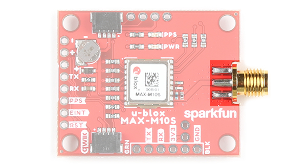
We've broken out the u-blox MAX-M10S module to a breakout. This section highlights the relevant features of the board. For more information about the IC, check out the Resources and Going Further.
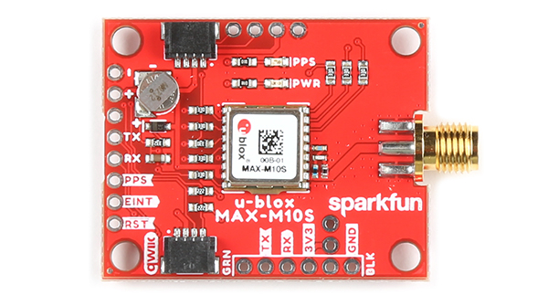
Power
Power for this board should be 3.3V. There is a 3.3V pin on the PTH header along the side of the board, but you can also provide power through the Qwiic connector.
 |
 |
| Top View | Bottom View |
Communication Ports
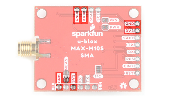
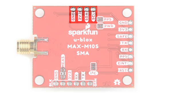
Qwiic and I2C (a.k.a. DDC)
There are two PTHs labeled SDA and SCL which indicates the I2C data lines. Similarly, you can just use the Qwiic connector to provide power and connect to the I2C pins. The Qwiic ecosystem is made for fast prototyping by removing the need for soldering. All you need to do is plug a Qwiic cable into the Qwiic connector and voila!
 |
 |
| Top View | Bottom View |
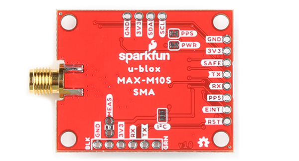
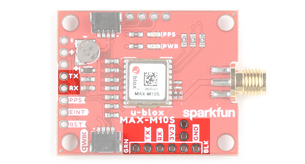
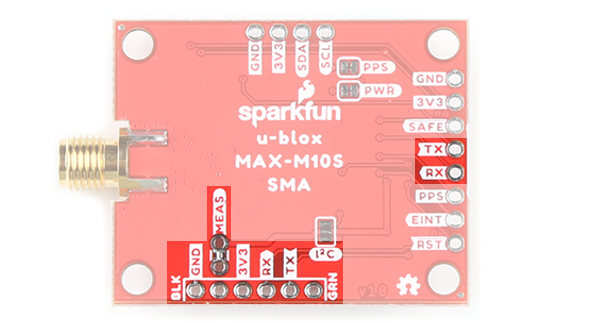
UART
For users that prefer to communicate over UART, we made sure to configure the UART pin grouping to an industry standard to ensure that it easily connects to a Serial Basic. Extra UART pins are also broken out on another edge of the board as well. The port is set to 38400 baud as the default.
 |
 |
| Top View | Bottom View |
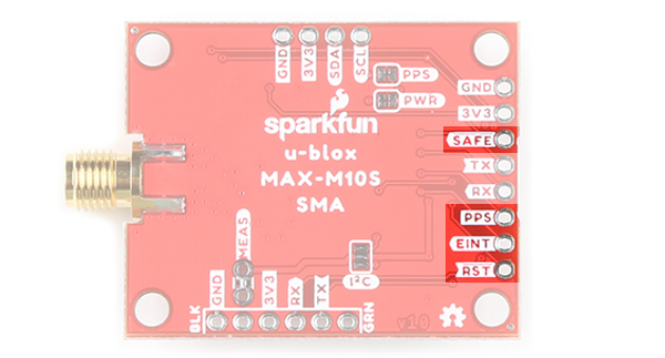
Control Pins
These pins are used for various extra control of the MAX-M10S. The control pins are highlighted below.
 |
|
| Top View | Bottom View |
- PPS: Pulse-per-second output pin. Begins blinking at 1Hz when module gets basic GPS/GNSS position lock.
- RST: Reset input pin. Pull this line low to reset the module.
- SAFE: Safeboot input pin. This is required for firmware updates to the module and generally should not be used or connected. To save on space, the silkscreen is labeled on the bottom of the board.
- EINT: Interrupt input/output pin. Can be configured using U-Center to bring the module out of deep sleep or to output an interrupt for various module states.
SMA Connector for Antenna
The board is populated with an SMA connector for a secure connection to a patch antenna.
LEDs
The board includes two status LEDs as indicated in the image below.
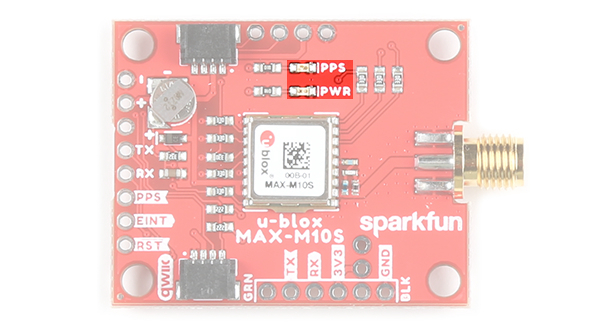
- PPS: The pulse per second LED will illuminate each second once a position lock has been achieved.
- PWR: The power LED will illuminate when 3.3V is provided either over the Qwiic bus or any of the 3.3V PTH pins.
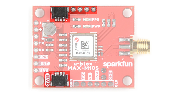
Jumpers
There are four jumpers on the back of the board. For more information, check out our tutorial on working with jumper pads and PCB traces should you decide to cut the traces with a hobby knife.
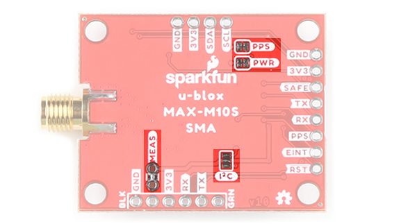
- PWR: This is connected to the PWR LED on the top of the board. Cutting this disables the LED.
- MEAS: Short for current measurement. By default, the MEAs is closed. Cutting the jumper and soldering to the PTH pads will allows you to insert a current meter and precisely monitor the how much current your application is consuming.
- PPS: This is connected to the PPS LED on the top of the board. Cutting this disables the LED.
- I2C: The I2C jumpers are open by default. By adding solder to the jumpers, it will connect to the 2.2kΩ pull-up resistors for the I2C bus. Most of the time you can leave these alone unless your project requires you to connect the pull-up resistors.
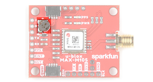
Backup Battery
The MS621FE rechargeable battery maintains the battery backed RAM (BBR) on the GNSS module. This allows for much faster position locks (a.k.a. hot start). The BBR is also used for module configuration retention. The battery is automatically trickle charged when power is applied and should maintain settings and GNSS orbit data for up to two weeks without power.
Board Dimensions
The overall length and width with the antenna connector is about 1.74" x 1.20". There are four mounting holes by each corner of the board.
