GNSS Receiver Breakout - MAX-M10S (Qwiic) Hookup Guide
 bboyho
Hardware Assembly
At a minimum, you will need to attach an external antenna to the MAX-M10S, supply 3.3V power, and connect to one of the board's peripherals.
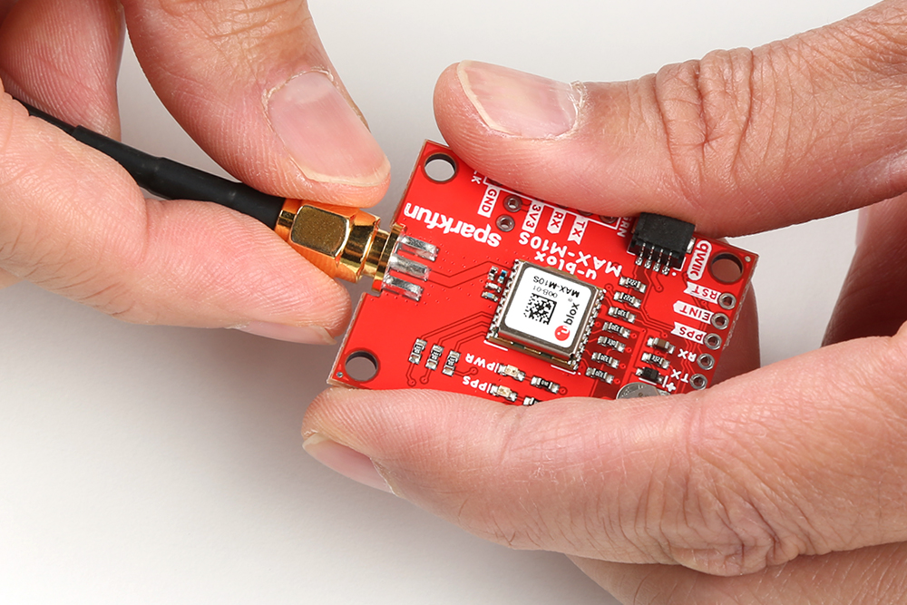
Attaching an External Antenna
Plug in one of our patch antennas with SMA connector to the GPS board. Secure the connection using the hex nut until it is finger-tight.
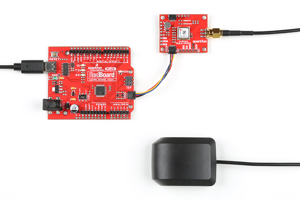
I2C
One method to communicate with the MAX-M10S is through I2C. The Qwiic connect system makes it quick and easy to connect the board to your system using a polarized cable. For embedded projects, you can use a Qwiic-enabled Arduino development board like the RedBoard Plus and its associated USB cable. Then plug a Qwiic cable between the RedBoard Plus and the SparkFun MAX-M10S.
If you're going to be soldering to the through hole pins for I2C functionality, then just attach the following lines between your chosen microcontroller's I2C and the MAX-M10S:
- SDA to SDA
- SCL to SCL
- 3.3V to 3.3V
- GND to GND
UART
A second method to communicate with the MAX-M10S is through its serial UART. You can directly connect the GPS to the computer by connecting a USB-to-serial converter to the industry standard serial connection (aka the 'FTDI' pinout). In this case, we used an CH340 but you can use another USB-to-serial converter like an FTDI. Just make sure to match the silkscreen (GRN to GRN and BLK to BLK). For a secure connection, you'll need to solder male header pins or wires to the MAX-M10S.

You could also connect the pins to a microcontroller like the RedBoard Plus as long as the switch for the logic levels are flipped to the 3.3V side before powering the board up. You'll need to do a little bit more work as opposed to using Qwiic connect system. You'll need to attach the following lines between your chosen microcontroller's UART and the MAX-M10S:
- Tx to Rx
- Rx to Tx
- 3.3V to 3.3V
- GND to GND