GNSS Chip Antenna Hookup Guide
 Nate
Nate 
Hardware Overview
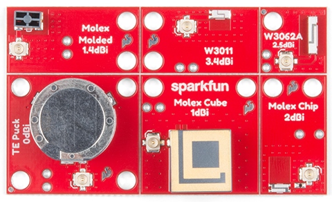
The SparkFun GNSS Chip Antenna Evaluation Board is composed of six ‘blocks’. Each one is capable of obtaining a GPS lock but the reception quality depends on the size and shape of the antenna.
Antenna Technologies
There are six different antennas on the GNSS Chip Antenna Evaluation Board.
You can find the datasheet and technical information for each, in order from top left to lower right:
- Molex Molded - 1.4dBi
- Pulse W3011 - 3.4dBi
- Pulse W3062A - 2.5dBi
- TE Puck - 0dBi
- Molex Cube - 1dBi
- Molex Chip - 2dBi
The gain is printed on each antenna block but take this gain with a grain of salt. Antenna manufacturers tend to report the theoretical gain of an antenna, or the gain achieved from a more-than-ideal setup (i.e., using a ground plane the size of your head).
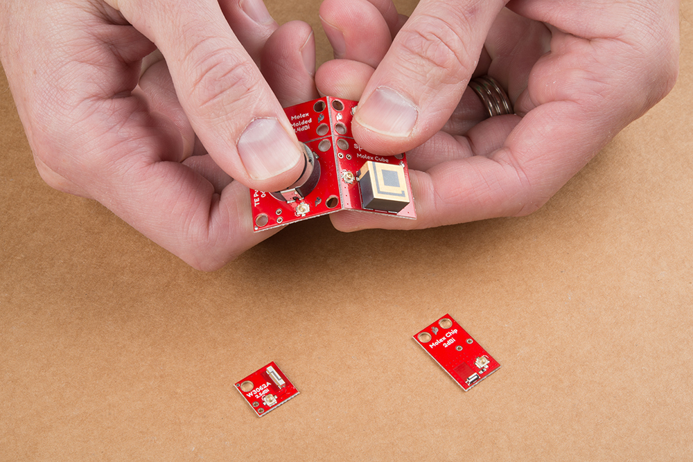
Individual Antenna Blocks
Each of the six antennas has its own U.FL connector, mounting holes, U.FL stress relief holes, and an isolated ground plane.
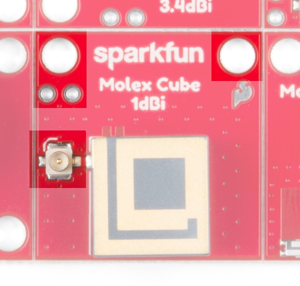
The board comes as a single unit but can be snapped apart so that any one antenna block can be mounted into a project. In theory the antennas should perform better separated but we found no measurable performance difference between the antennas as a whole or broken apart.
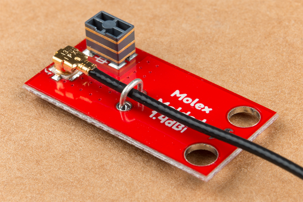
U.FL Connectors and Stress Relief
U.FL connectors are generally pretty resilient but if you’ve got a particularly wearable project or harsh antenna environment, you can reinforce the U.FL connection by soldering a piece of wire over the cable to hold it in place. We recommend you do this after you’ve selected the antenna that best suits your project.