GNSS Chip Antenna Hookup Guide
Introduction
GPS is common but what if you need to pack your GPS receiver into a small space such as a wearable? Standard GPS antennas are much too large to strap to your wrist so what do you do? You use one of the SparkFun GNSS Chip Antennas!
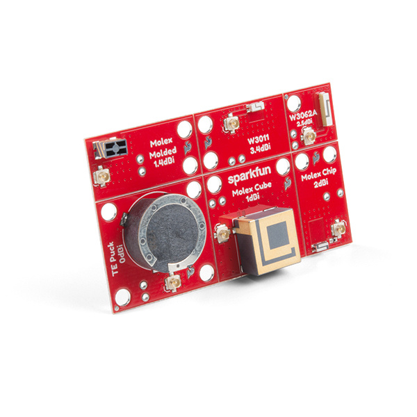
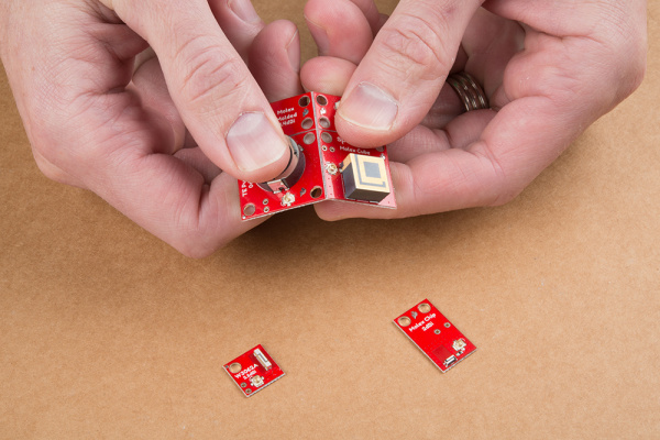
The SparkFun GNSS Chip Antenna Evaluation Board makes it easy to test out various sized GPS antennas and geometries. These individual antennas can even be separated and installed permanently into a project once you select the best one for your application.
Required Materials
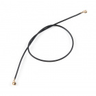
The GNSS Chip Antenna Evaluation Board (we’ll call it the eval board from here on out for your tongues’ sake) is possible because we have designed each antenna to have a 50-ohm microstrip. To connect, you’ll need a U.FL cable and a GPS receiver capable of connecting to a U.FL cable. You may not need everything though depending on what you have. Add it to your cart, read through the guides, and adjust the cart as necessary.
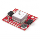
Below is a list of SparkFun GPS receivers that have a U.FL connector for its antenna. These are the easiest products to get working with the eval board.
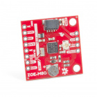
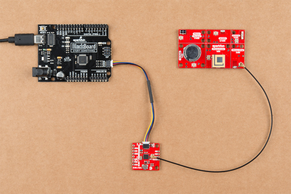
One of the most common setups is shown below. The ZOE-M8Q has a U.FL connector and can be attached to any of the six chip-scale GPS antennas.
Suggested Reading
If you’re unfamiliar with working with GPS receivers or U.FL connectors, be sure to checkout some of these foundational tutorials. You'll also need to check out the respective tutorials for your GPS receiver.
GPS Basics
Three Quick Tips About Using U.FL
Hardware Overview
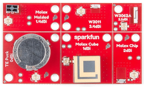
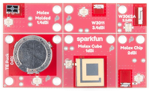
The SparkFun GNSS Chip Antenna Evaluation Board is composed of six ‘blocks’. Each one is capable of obtaining a GPS lock but the reception quality depends on the size and shape of the antenna.
Antenna Technologies
There are six different antennas on the GNSS Chip Antenna Evaluation Board.
You can find the datasheet and technical information for each, in order from top left to lower right:
- Molex Molded - 1.4dBi
- Pulse W3011 - 3.4dBi
- Pulse W3062A - 2.5dBi
- TE Puck - 0dBi
- Molex Cube - 1dBi
- Molex Chip - 2dBi
The gain is printed on each antenna block but take this gain with a grain of salt. Antenna manufacturers tend to report the theoretical gain of an antenna, or the gain achieved from a more-than-ideal setup (i.e., using a ground plane the size of your head).
Individual Antenna Blocks
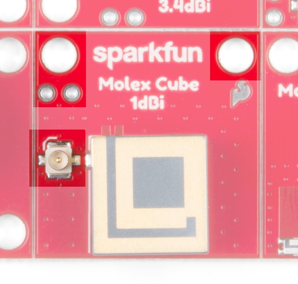
Each of the six antennas has its own U.FL connector, mounting holes, U.FL stress relief holes, and an isolated ground plane.
The board comes as a single unit but can be snapped apart so that any one antenna block can be mounted into a project. In theory the antennas should perform better separated but we found no measurable performance difference between the antennas as a whole or broken apart.
U.FL Connectors and Stress Relief
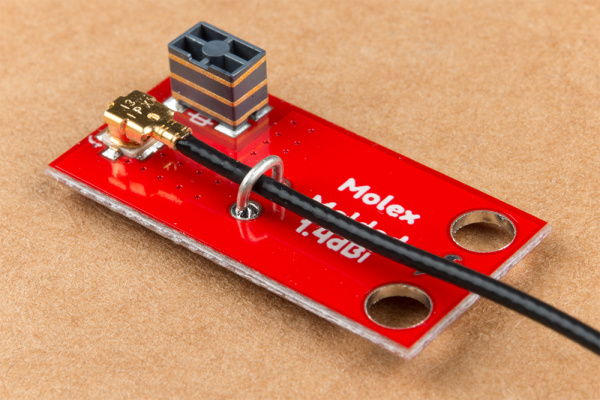
U.FL connectors are generally pretty resilient but if you’ve got a particularly wearable project or harsh antenna environment, you can reinforce the U.FL connection by soldering a piece of wire over the cable to hold it in place. We recommend you do this after you’ve selected the antenna that best suits your project.
How Well Do the Antennas Perform?
Here’s our preliminary findings:
| Antenna Name | SIV[1] | PDOP[2] | HDOP[3] |
|---|---|---|---|
| Molex Molded | 5 | 2.2 | 1 |
| W3011 | 9 | 1.47 | 0.69 |
| W3062A | 6 | 2.48 | 1.16 |
| Molex Chip | 5 | 2.27 | 1.18 |
| Molex Cube | 10 | 1.16 | 0.63 |
| TE Puck | 9 | 1.27 | 0.68 |
| Molex Flexible[4] | 10 | 1.14 | 0.62 |
1 - Satellites in view: The number of satellites an antenna was able to detect after 60 seconds of searching. Higher is generally better.
2 - Position Dilution of Precision: The accuracy of the 3D solution being output by the receiver. A lower number is better. Meaning of numbers can be found on Wikipedia.
3 - Horizontal Dilution of Precision: The accuracy of the horizontal location solution being output by the receiver. A lower number is better. Meaning of numbers can be found on Wikipedia.
4 - The Flexible Adhesive GPS Antenna is not on the GNSS Chip Antenna Evaluation Board but performed impressively.
These results are provided for illustration only. Testing was done using a Ublox ZED-F9P on the RTK2 with 60 seconds to obtain satellites from a cold start. Your results will vary greatly based on how clear your view is of the sky, where you are located, and the type of GPS receiver used.
As you can see, the larger antennas tend to pick up more satellites. The interesting outliers are the flexible antenna (arguably the largest of all the antennas) and the Pulse W3011 (arguably one of the smallest, best performing antennas).
FAQ and Troubleshooting
What’s the Difference Between GPS and GNSS?
GPS refers to the collection of satellites put into space by the USA. Other countries have their own collection of navigation satellites include Russia (their constellation is called GLONASS), the EU (Galileo), and China (BeiDou). GNSS refers to all navigation constellations as a whole. The GNSS Chip Antenna Evaluation Board is capable of receiving signals from any GPS/GLONASS/BeiDou/Galileo satellite transmitting on band 1 (the most common civilian frequency). If your GPS receiver was purchased after 2015 it will probably be capable of picking up most GNSS satellites.
I’m Not Getting a Lock?!
Are you outside? Do you have a clear, unobstructed view of the sky? These antennas are small and require a very clear view of the sky. They can not get a lock indoors.
Have you moved outside and are still having problems? Double check that your U.FL connections are seated nicely and orthogonal. You should feel a nice click when the connector is seated properly. Be sure to checkout our tutorial on using U.FL connectors for more info.
Three Quick Tips About Using U.FL
Resources and Going Further
We hope you have fun experimenting with your chip antennas. We find the variance in design and geometries fascinating as is the art of antenna design. Remember, all our designs are open source so you are welcome to use the footprints and layouts from our board in your own design. That’s the real power of this eval board - try out various antennas and if you like one you can implement it in your own tiny GPS receiver design!
For more information, check out the resources below:
- Schematic (PDF)
- Eagle Files (ZIP)
- Datasheets (PDF)
- GitHub Product Repo - Check out the repo for the latest hardware files.
- SFE Product Showcase
Be sure to check out some of the other tutorials we have around GPS:
