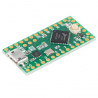
Getting Started with the Teensy
Hardware Overview
Each Teensy board has its own key features which are highlighted here. For individual pinout diagrams and detailed schematic information, please check PJRC's page here. The pin functionality for each version is can be different so make sure to check before switching versions.
For full specifications and detailed comparison chart of the Teensy, check out respective product pages or the Teensy Technical Specifications page.
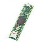
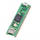
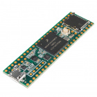
Teensy 4.1
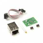
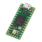
The Teensy 4.1 builds on the Teensy 4.0. The size is uses the same size and footprint as the Teensy 3.5/3.6. Most technical specifications are the same as the Teensy 4.0 except with a few expanded features. Some of the more notable features include pins for Ethernet port (10 / 100 Mbit DP83825 PHY), host USB port, options to expand memory with two locations to solder SOIC memory chips, and a microSD card socket. This runs off of the NXP iMXRT1062 IC, which is a 32-bit ARM Cortex-M7. It is 3.3V tolerant only on its I/O pins.
| Feature | Number Available |
|---|---|
| PWM | 35 |
| Analog In | 18 |
| I/O | 55 |
| Serial Port | 8 |
| I2C Port | 3 |
| SPI Port | 8 |
| Real Time Clock | 1 |
| Flash | 8MB (64K reserved for recovery & EEPROM emulation) |
| RAM | 1024K (512K is tightly coupled) |
Teensy 4.0
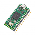
The Teensy 4.0 is the same size and footprint as the Teensy 3.1/LC but even more powerful with its whopping 600MHz clock speed! The pin functionality is slightly different compared to the other versions. This runs off of the NXP iMXRT1062 IC, which is a 32-bit ARM Cortex-M7. It is 3.3V tolerant only on its I/O pins.
| Feature | Number Available |
|---|---|
| PWM | 31 |
| Analog In | 14 |
| I/O | 40 |
| Serial Port | 7 |
| I2C Port | 3 |
| SPI Port | 3 |
| Real Time Clock | 1 |
| Flash | 2048K (64K reserved for recovery & EEPROM emulation) |
| RAM | 1024K (512K is tightly coupled) |
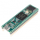
Teensy 3.6
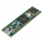
The Teensy 3.6 uses a similar pinout as the smaller Teensys. However, the board breaks out more pins and includes a microSD card socket. This runs off of the MK66FX1M0VMD18 IC, which is a 32-bit ARM Cortex-M4. It is 3.3V tolerant only on its I/O pins.
Teensy 3.6
DEV-14057Teensy 3.6 (Headers)
DEV-14058| Feature | Number Available |
|---|---|
| PWM | 22 |
| Analog In | 25 |
| I/O | 62 |
| Serial Port | 6 |
| I2C Port | 4 |
| SPI Port | 3 |
| Real Time Clock | 1 |
| Touch Sense pins | 11 |
| Flash | 1024K |
| RAM | 256K |
Teensy 3.5
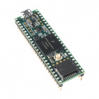
The Teensy 3.5 is similar to the 3.6. This runs off of the MK64FX512VMD12 IC, which is a 32-bit ARM Cortex-M4. It is 5V tolerant on its I/O pins.
Teensy 3.5
DEV-14055Teensy 3.5 (Headers)
DEV-14056| Feature | Number Available |
|---|---|
| PWM | 20 |
| Analog In | 27 |
| I/O | 62 |
| Serial Port | 6 |
| I2C Port | 3 |
| SPI Port | 3 |
| Real Time Clock | 1 |
| Touch Sense pins | 0 |
| Flash | 512K |
| RAM | 256K |
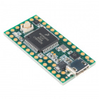
Teensy 3.2/3.1
The Teensy 3.2 is the same size and footprint as the Teensy LC but more powerful. This runs off of the MK20DX256 IC, which is a 32 bit ARM Cortex-M4. It is also 5V tolerant on its digital I/O pins and can provide up to 3.3V at 100mA to other devices. The analog pins are 3.3V tolerant only.
Teensy 3.2
DEV-13736| Feature | Number Available |
|---|---|
| PWM | 12 |
| Analog In | 21 |
| I/O | 34 |
| Serial Port | 3 |
| I2C Port | 2 |
| SPI Port | 1 |
| Real Time Clock | 1 |
| Touch Sense pins | 12 |
| Flash | 256K |
| RAM | 64K |
The pushbutton on the 3.1 is a reboot trigger and does not reset the entire system, similar to the pushbutton on the LC. In order to reset the board, you must access the RESET test point on the bottom of the board.
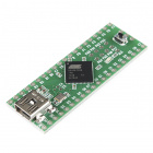
Teensy ++ 2.0
This Teensy board is the only AVR-based Teensy that SparkFun carries. It runs off of the AT90USB1286, an 8 bit AVR running at 16MHz. It also has the largest footprint of all of the Teensy boards, at 1.375 in2.
Teensy++ 2.0
DEV-11781| Feature | Number Available |
|---|---|
| PWM | 9 |
| Analog In | 8 |
| I/O | 46 |
| Serial Port | 1 |
| I2C Port | 1 |
| SPI Port | 1 |
| Flash | 128K |
| RAM | 8K |
The push button on the end of the Teensy 2.0 ++ is a RESET button. This is also used during programming the Teensy with Teensyduino, discussed later.
Teensy LC
The Teensy LC is 0.98 in2. It runs off of the 32 bit ARM Cortex-M0+ at 48MHz and runs at 3.3V.
The Digital to Analog converter is on pin A12 of the microcontroller. Pin 17 outputs voltages up to the supplied Vin voltage, at 8mA.
Pins D5, D16, D17 and D21 can source signals up to 20mA. All other pins are limited to 5mA.
Teensy LC
DEV-13305| Feature | Number Available |
|---|---|
| PWM | 10 |
| Analog In | 13 |
| I/O | 27 |
| Serial Port | 3 |
| I2C Port | 2 |
| SPI Port | 2 |
| Touch Sense Pins | 11 |
| Flash | 62K |
| RAM | 8K |
The pushbutton on the LC is not a reset button but instead triggers HalfKay mode. This allows the board to reboot to the newest code or accept new uploaded code.
